Welcome to the Chicago & North Western #1385 steam status blog! Follow along as we bring the 1907 American Locomotive Company 4-6-0 steam engine back to operating condition.
This post begins with a sound of a mystery device:
We’ve heard it here before. Now it is coming from a different place. First off, the sound must have a home.
Pete Deets photo.
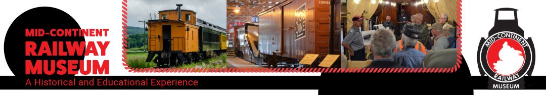
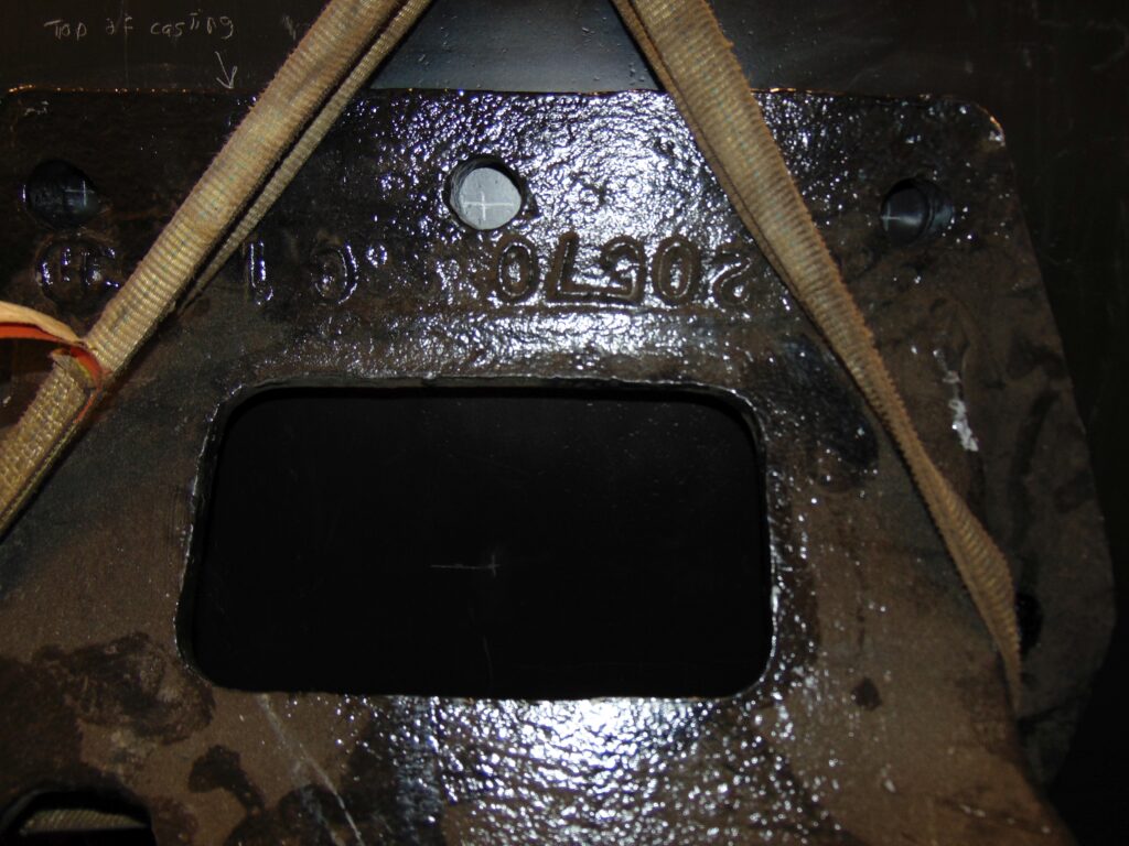
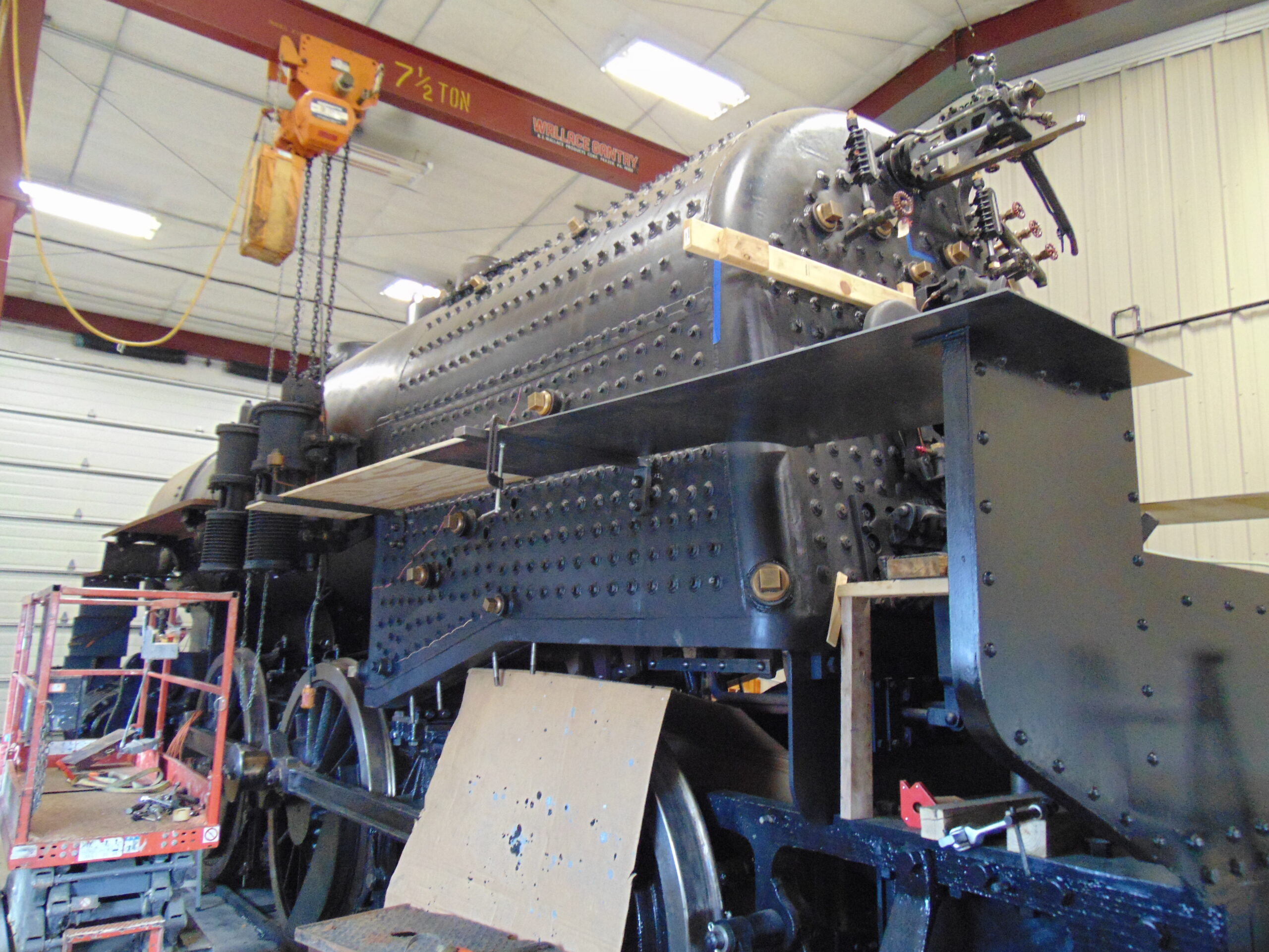
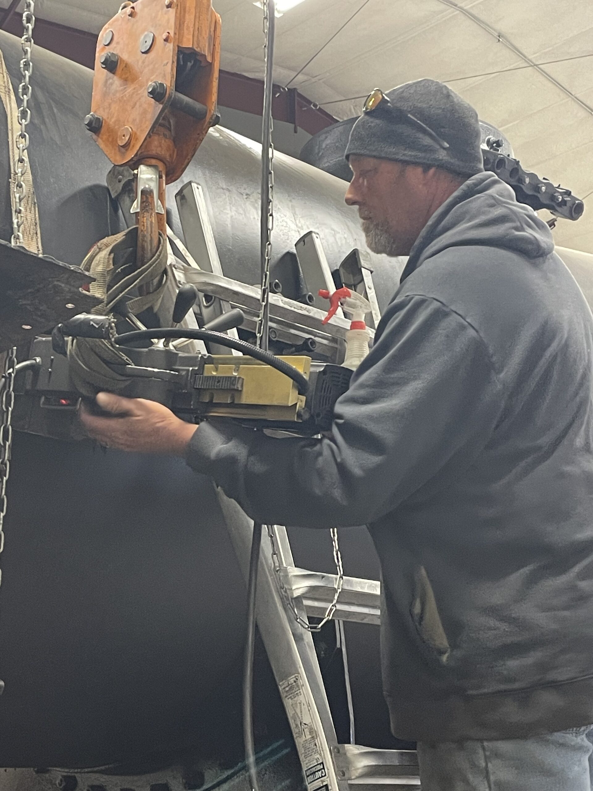
Here, Alex Therrien of FMW Solutions is checking the setup of the magnetic base drill that on the side of 1385’s boiler. You’ll hear much more about FMW’s involvement with 1385 at the spring Members’ meeting this weekend. The drill will be making the stud holes for the noisy device in question. Now, here are some photos of the mystery device:
Alex Therrien photo.
Alex Therrien photo.
Alex Therrien photo.
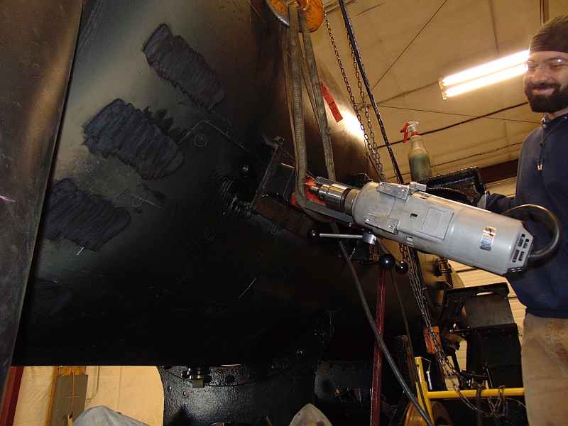
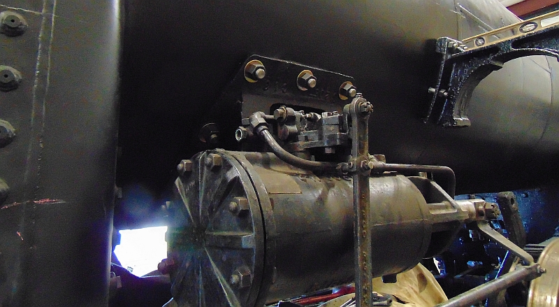
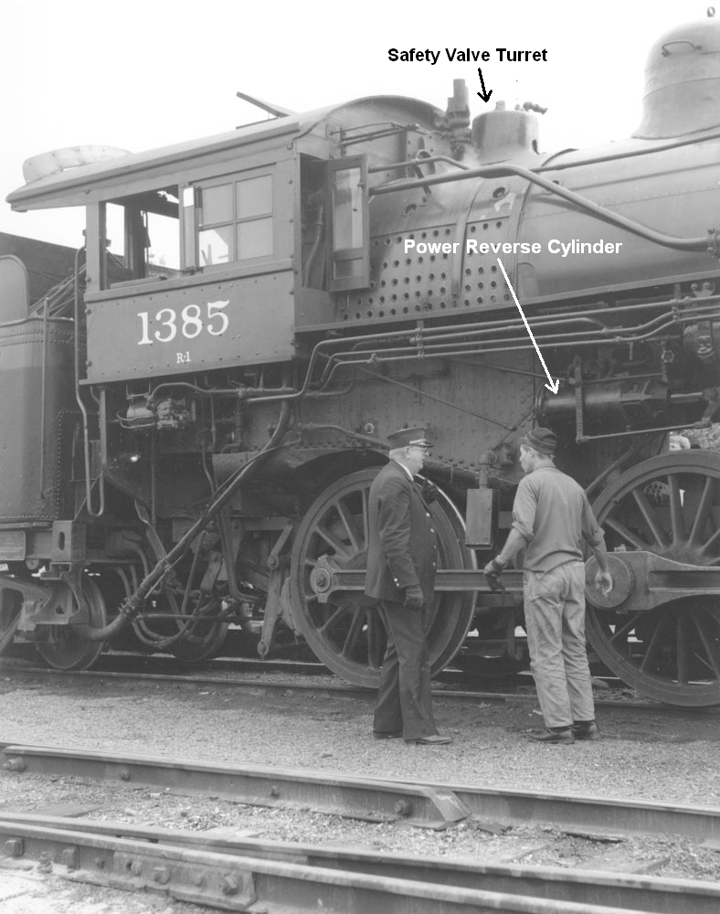
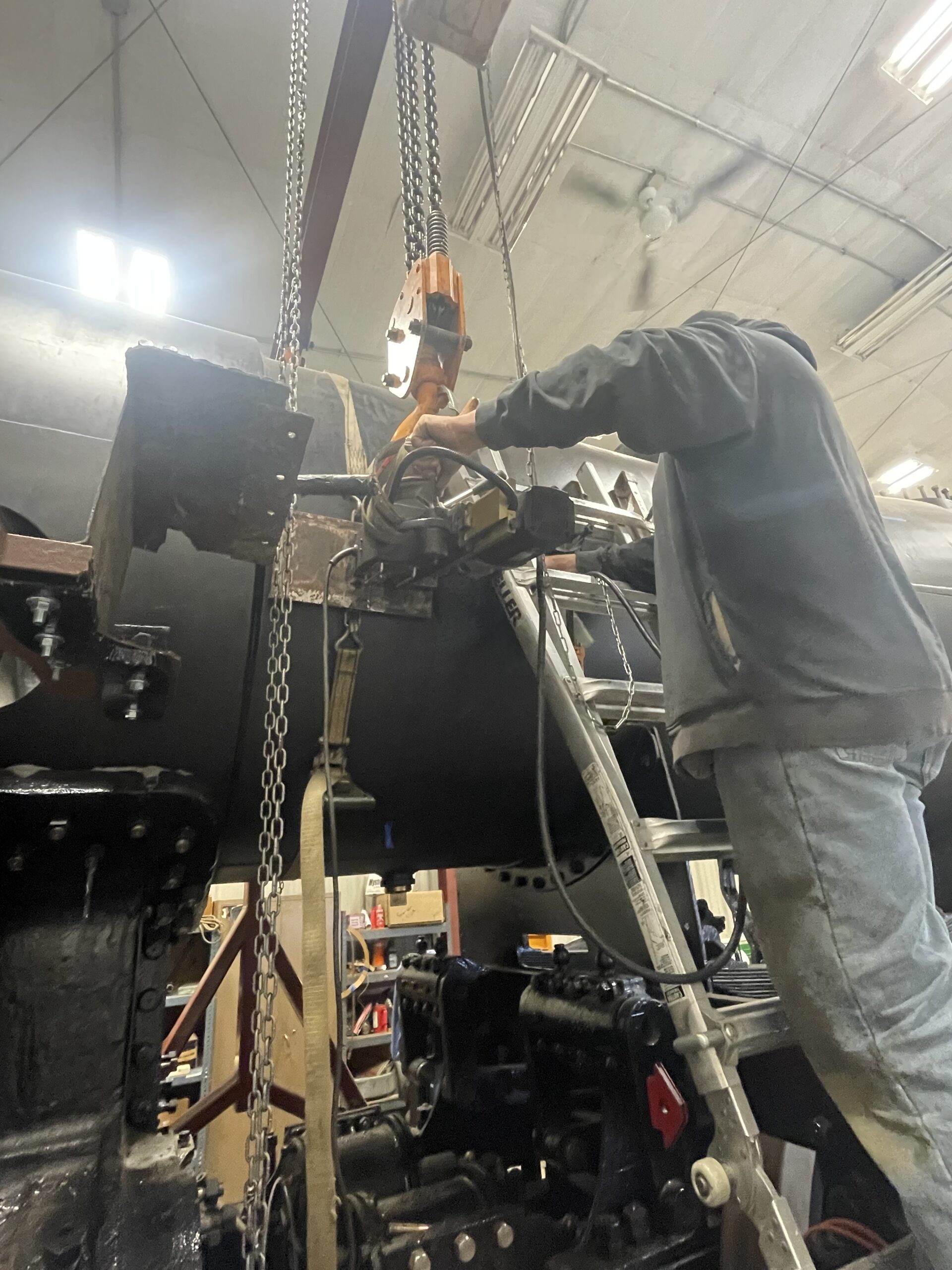
Have you guessed it yet? The familiar sound is the power reverse cylinder finding its permanent home on the boiler. Last time the power reverse was seen in an update was last autumn when the power reverse was undergoing repairs and was mounted to a forklift to allow testing.
Pete Deets photo.
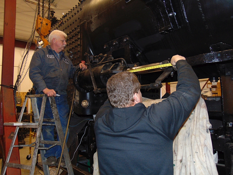
A test airline was run to the cylinder, and this shot, shows Steve Roudebush and Ed Ripp checking the length of the stroke of the piston rod. Here is a short video of Ed Ripp cycling the power reverse that will be used to control the direction of and how much power our beloved 1385 will create as she goes steaming down the track.
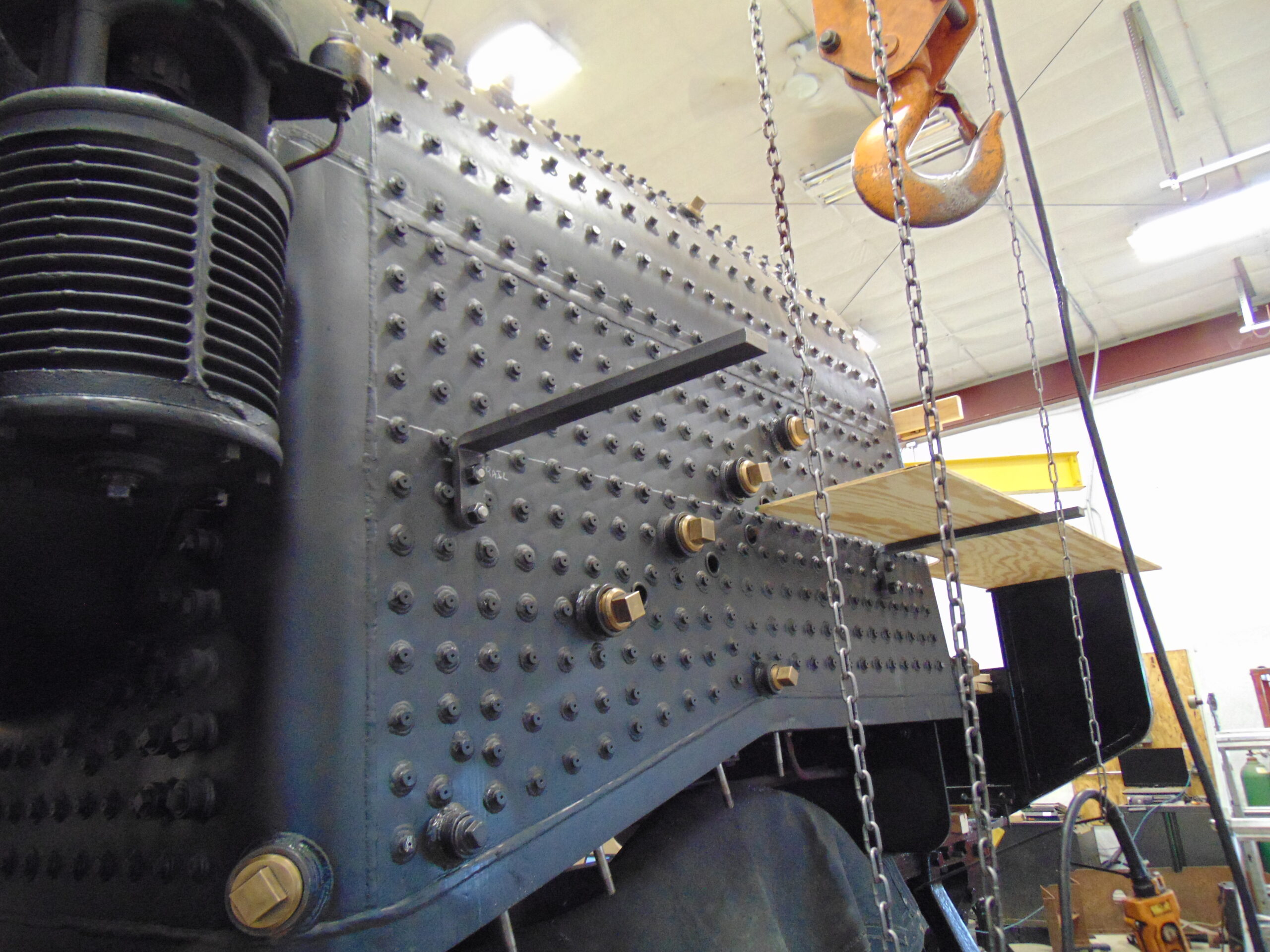
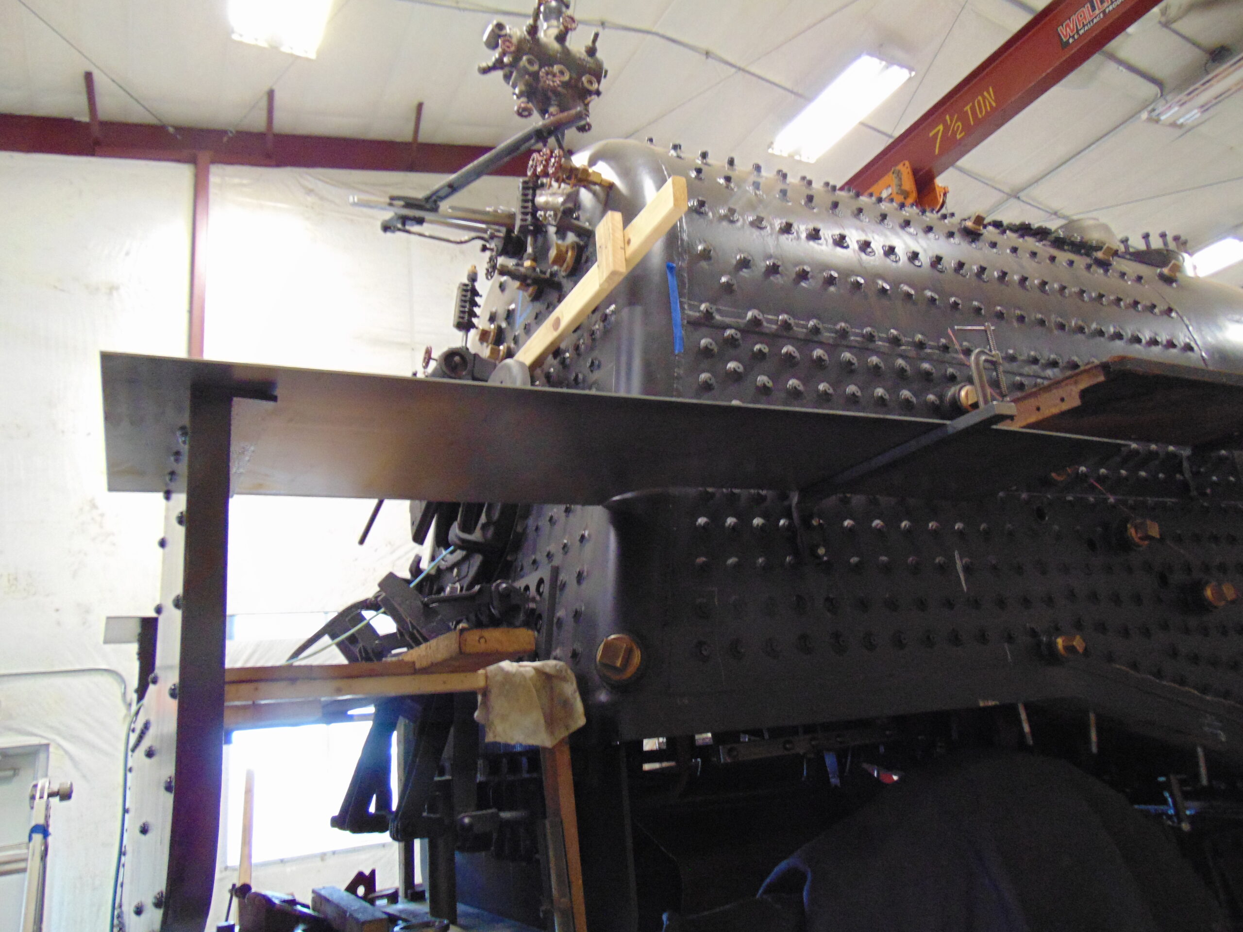
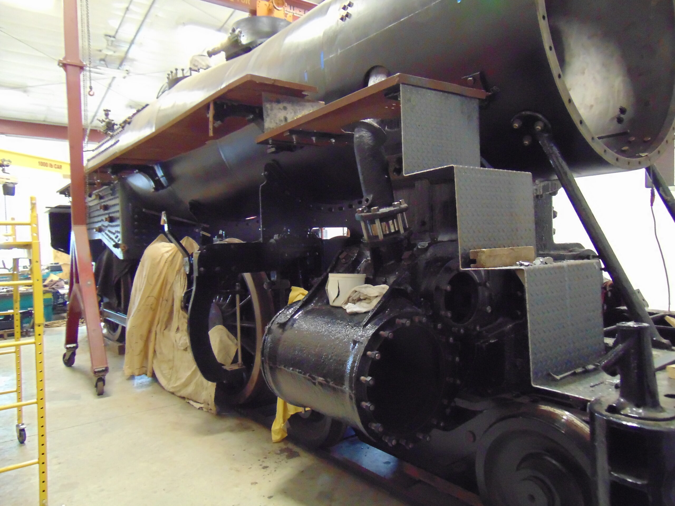
As mentioned in our last update, almost every item that must be mounted to the boiler of our engine requires at least one more hole to be drilled into the boiler shell. In recent weeks the layout of where to drill some of those holes has been moving quickly. Among those completed are the holes for mounting the bell and the steps used to access and fill the sand dome. Item locations laid out and awaiting attention include brackets for the Brake Control stand, Reverser, Steam Gauge, Safety Valve and Cab turrets, and the Power Reverse Cylinder.
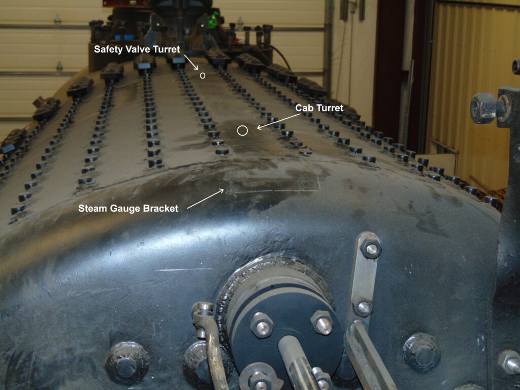
Pete Deets photo.
Starting at the top of the boiler, the rectangle at the near edge is where the Steam Gauge bracket will be mounted, and further back will be the Cab and then the Safety Valve turrets.
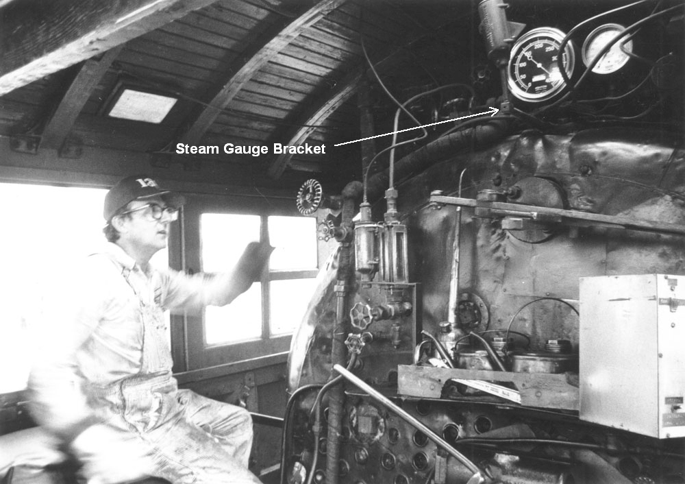
Jerry Parr, Mid-Continent fireman, in cab of C&NW 1385 at Mason City, IA, 6/26/1983. Paul Swanson photo.
From Paul Swanson’s collection, here is the Steam Gauge location.
C&NW 1385 at North Freedom, WI. 9/17/1988. R.A. Oom photo. Paul Swanson collection.
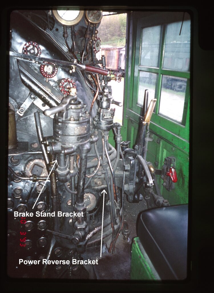
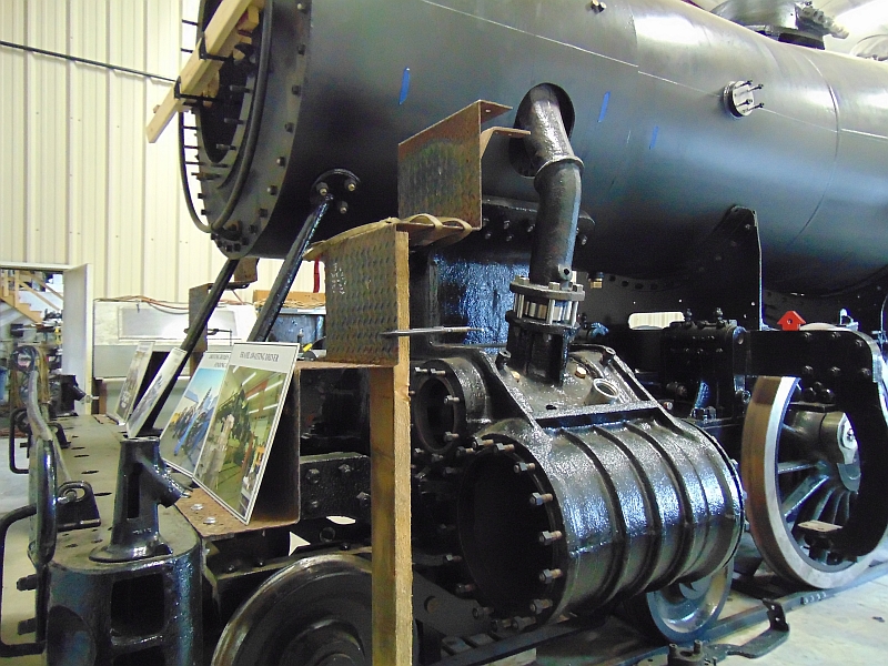
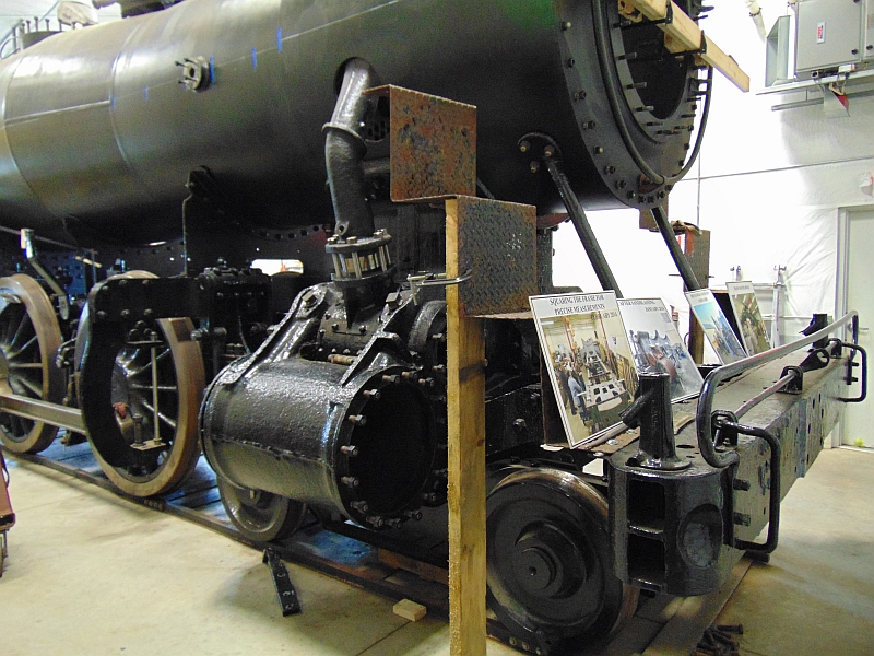
The Cab Turret is hidden behind the gauge, but the Safety Valve Turret can be seen in this shot, along with the Power Reverse Cylinder. The Power Reverse system uses an air-powered cylinder controlled by a lever in the cab to actually move the valve gear of the engine and control both the direction the engine moves and how much power is applied to the rails.
Pete Deets photo. Pete Deets photo.
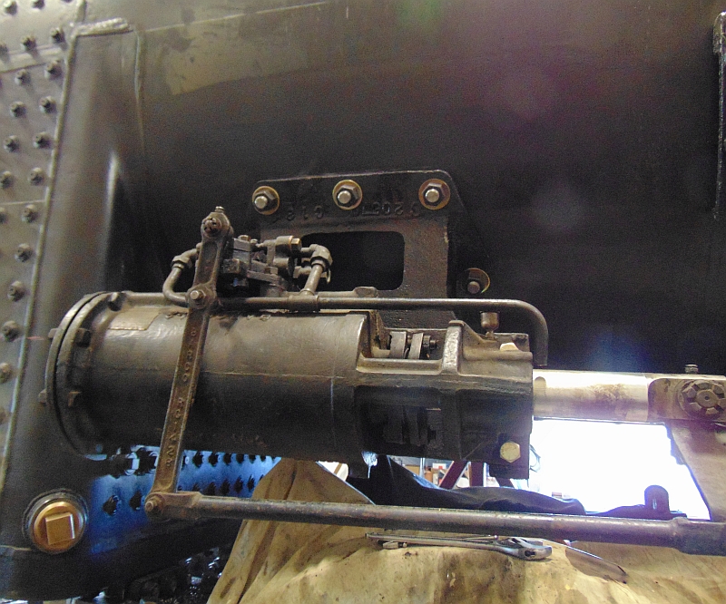
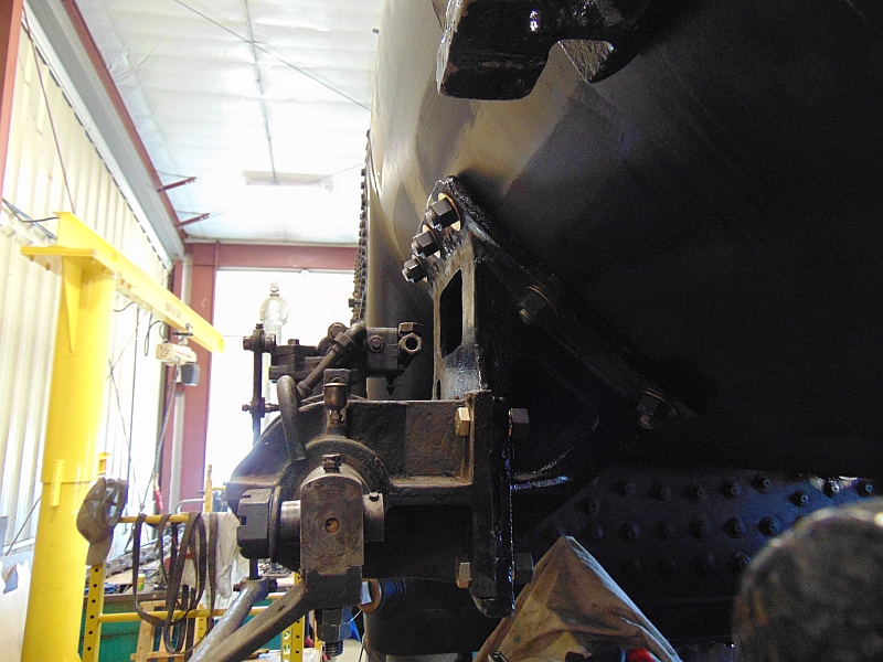
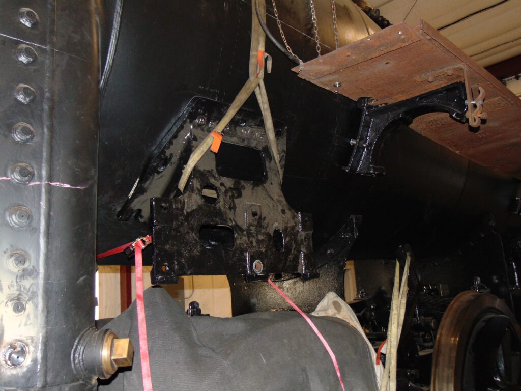
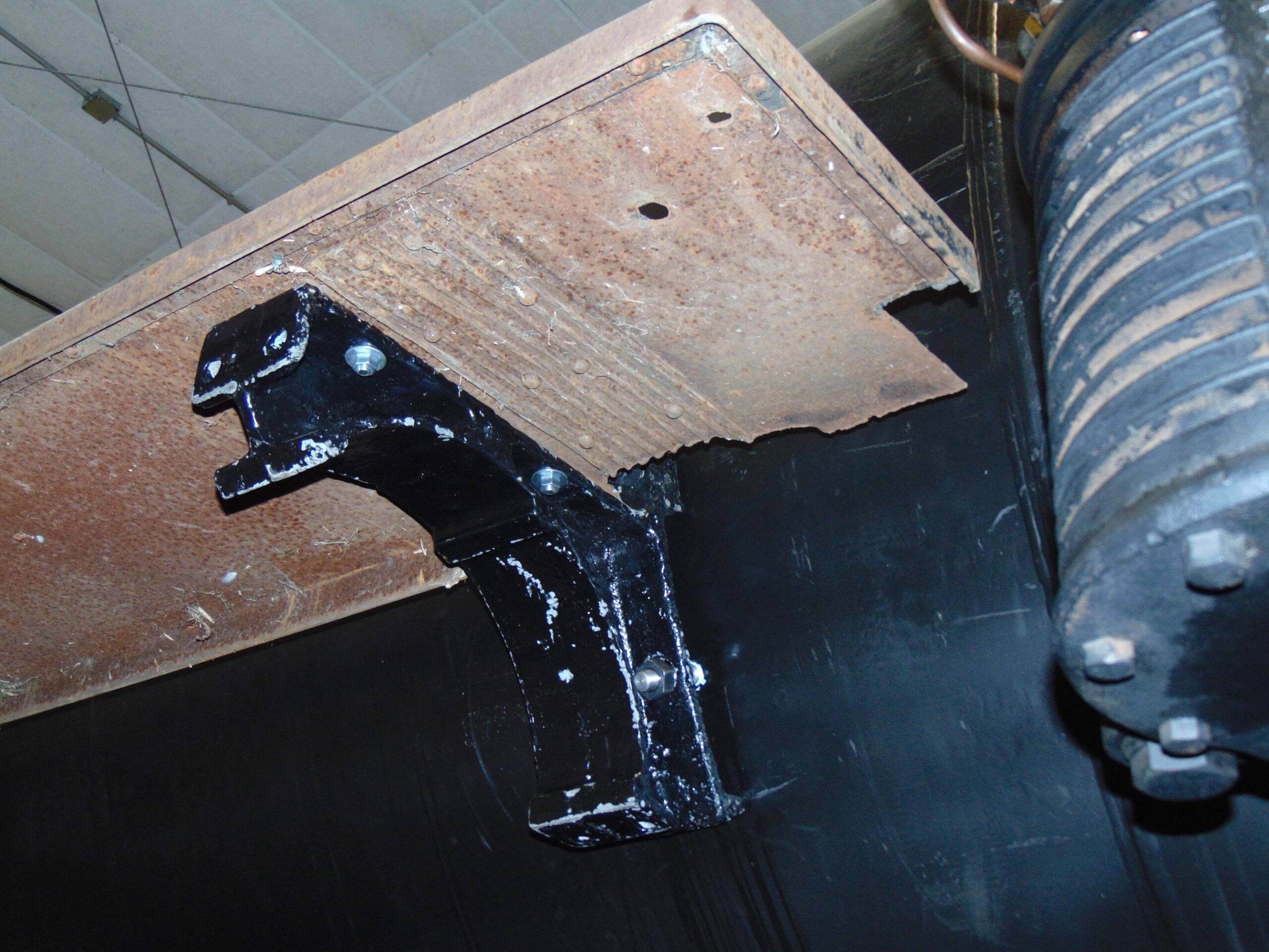
The cylinder is mounted outside the cab to this bracket and the bracket is held to the boiler shell by 7 studs. The locations for the holes were laid out using dimensions from the C&NW drawings we have, but then the bracket is strapped to the boiler so the actual locations can be transferred from the bracket itself. In several places we’ve found manufacturing differences between the drawings and the actual parts which makes double and triple checking necessary.
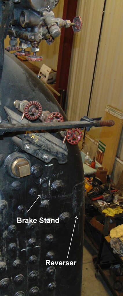
Air Brake Stand and Reverser Lever locations, 2024. Pete Deets photo. Air Brake Stand and Reverser Lever, 1993. Unkown photographer.
Inside the cab once again, we see the locations for the Air Brake Stand and the Reverser Lever as well as a photo from 1993 showing the actual items. The process of 3-D chess continues as we move ever closer to the FRA-mandated boiler tests.
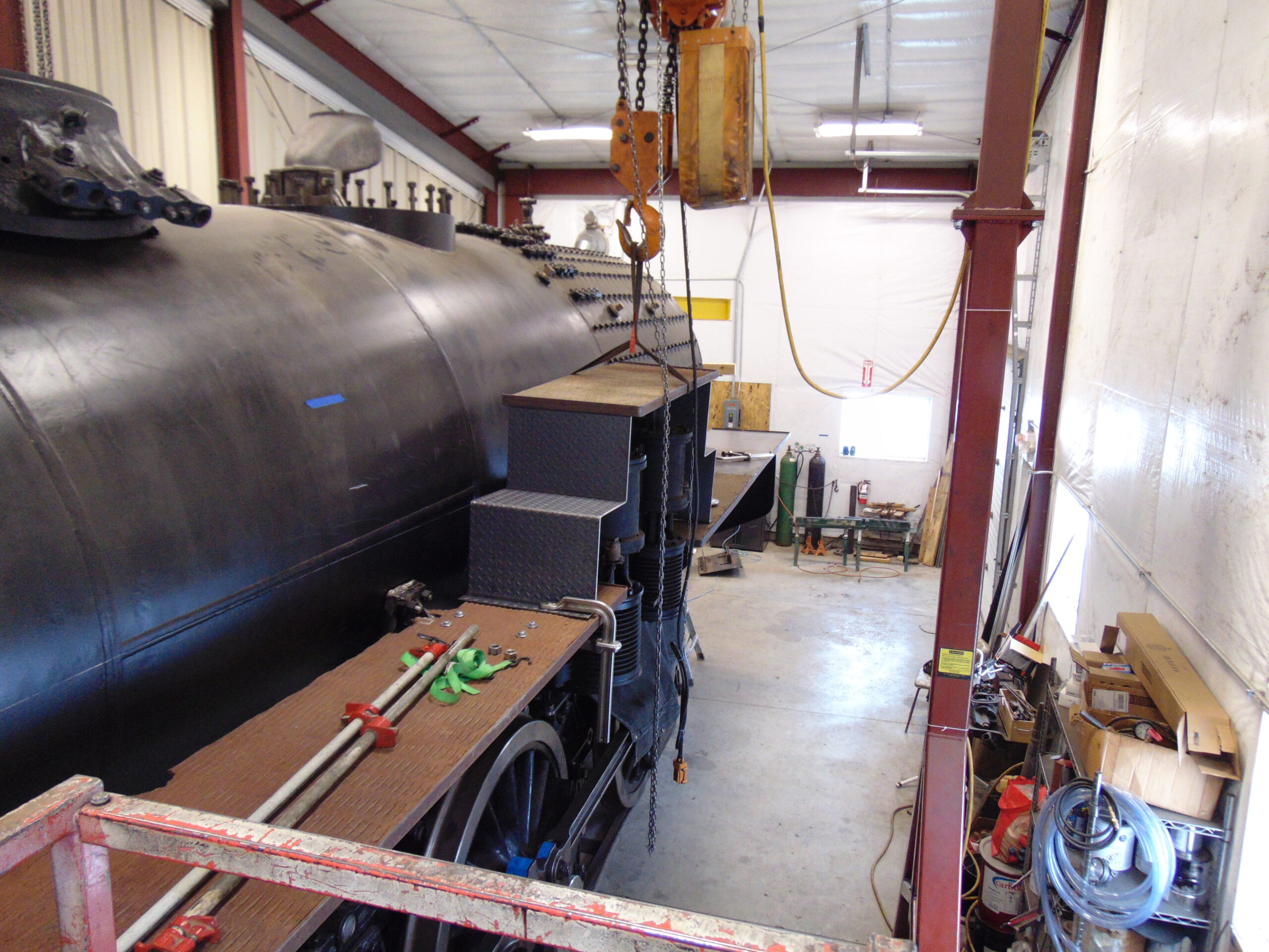
The runboards and handrails on a steam locomotive are necessary appliances that allow the crew to inspect and service many other appliances attached to the boiler. These include the locomotive’s air pumps, bell and ringer, sand dome, and generator. On the Chicago & North Western no. 1385 an extension of the runboards also becomes the cab floor/support so the 3-D puzzle-solving of the locomotive’s reassembly stage continues. For this update, we’ll stay on the runboards and address the handrails in the near future.
Installing the runboards and handrails now is important for two reasons. First, every bracket, support, or stanchion is attached to the boiler with studs and each of those studs requires another hole in the boiler to be drilled and threaded. As part of the Federal Railroad Administration (FRA) inspections to bring a locomotive back into active service, the boiler is pressurized with water and every penetration of the boiler must be tight and with no leaks. This inspection using pressurized water is called the hydrostatic test and must be passed before we can fire the boiler for the initial steam tests.
The other major reason for installing runboards and handrails now is it will make the remaining work on the top area of the boiler much easier. It will also make access much safer with a more stable platform to use.
There are a pair of brackets on the smokebox that hold the lower step over the cylinders and then a pair on the boiler proper. The front pair of brackets on each side of the boiler proper are tasked with double duty.
They are also the mounting brackets for the air reservoirs which account for their size and shape. The reservoir is held into the crescent shape by a pair of straps that go around the tank and then are bolted to the top & bottom of the bracket.
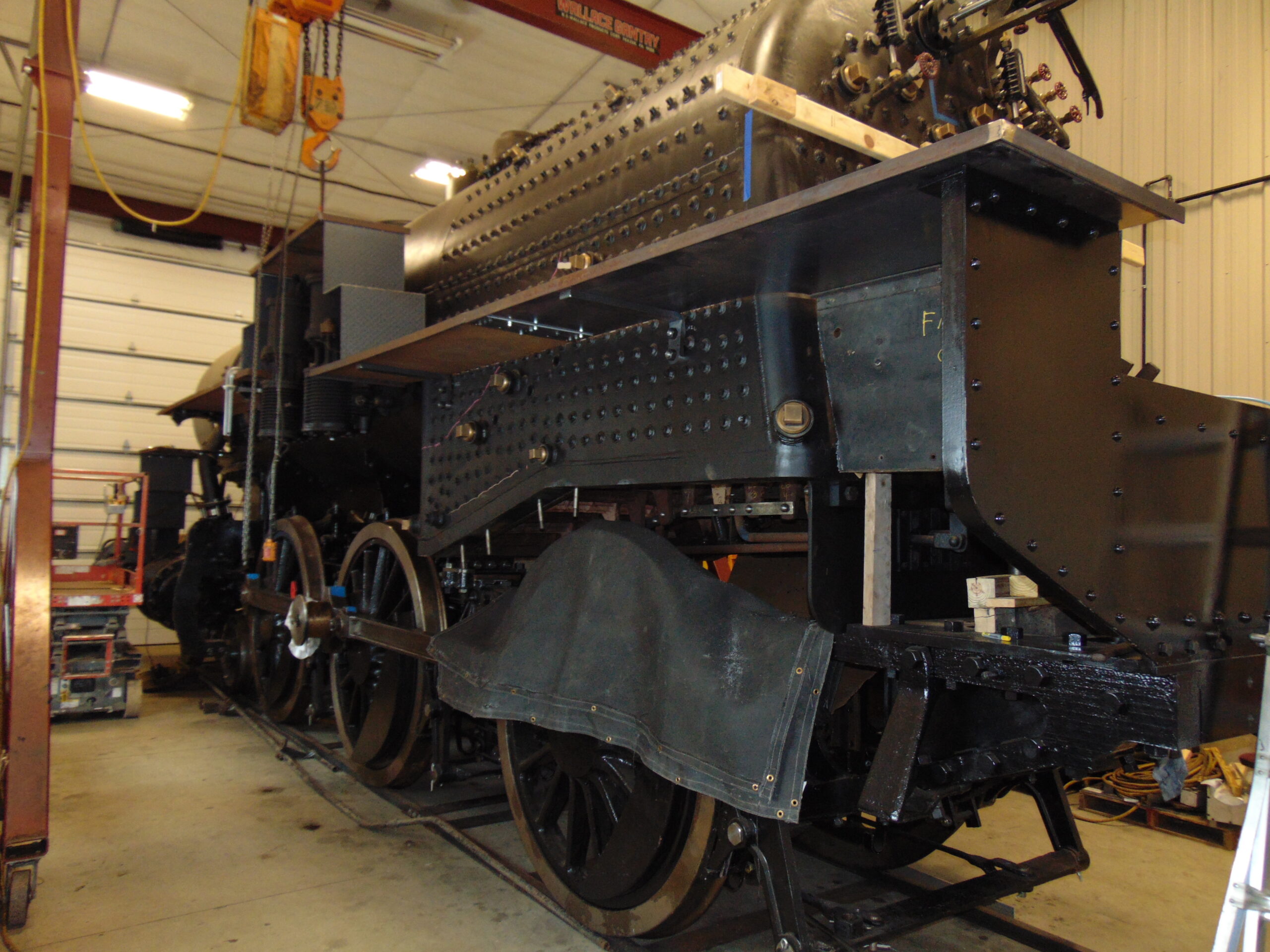
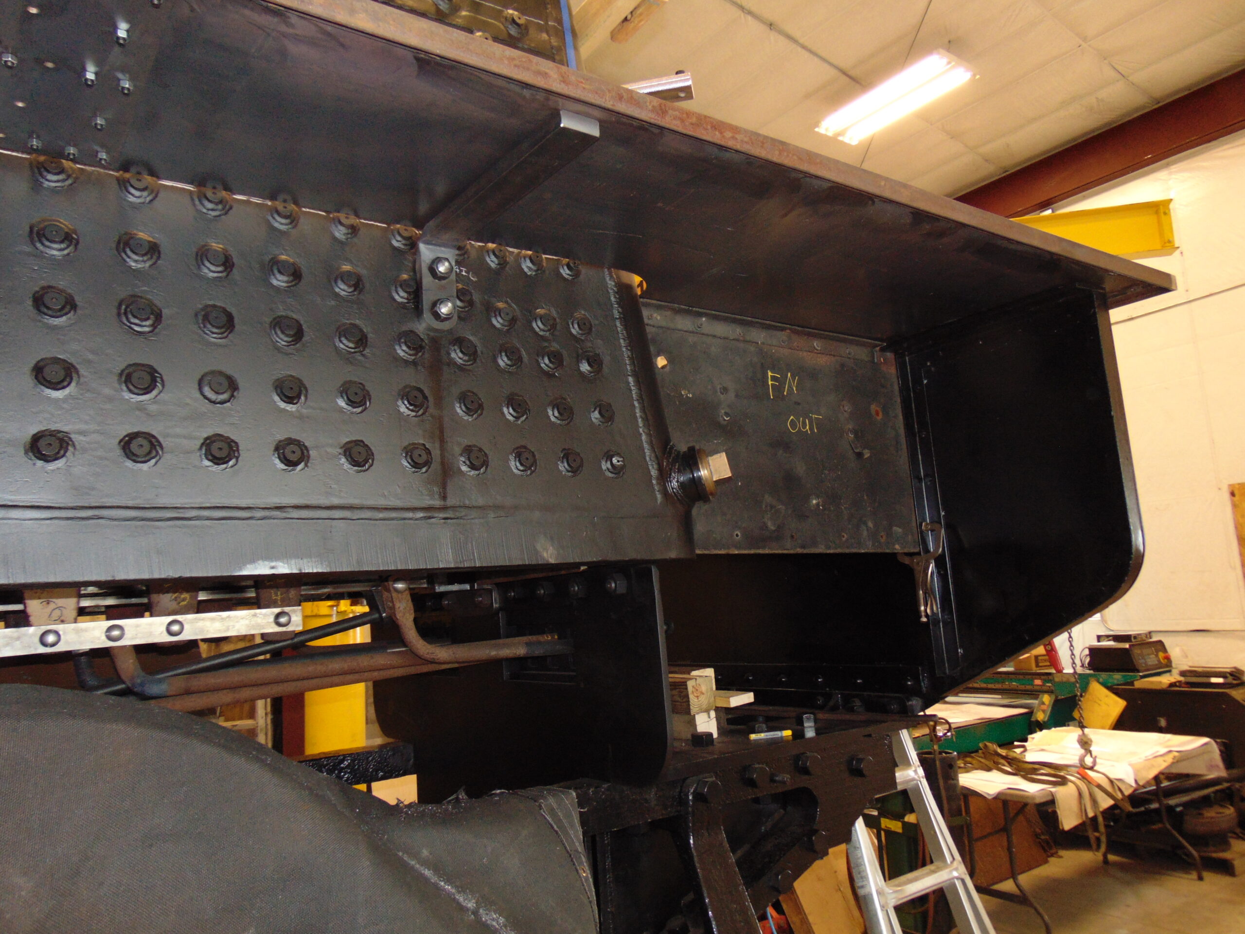
Behind the air compressors, two brackets are studded to the firebox sidesheets which will hold the runboard and the front of the cab while the rear of the cab is held up by a bracket on the end of the engine frame.
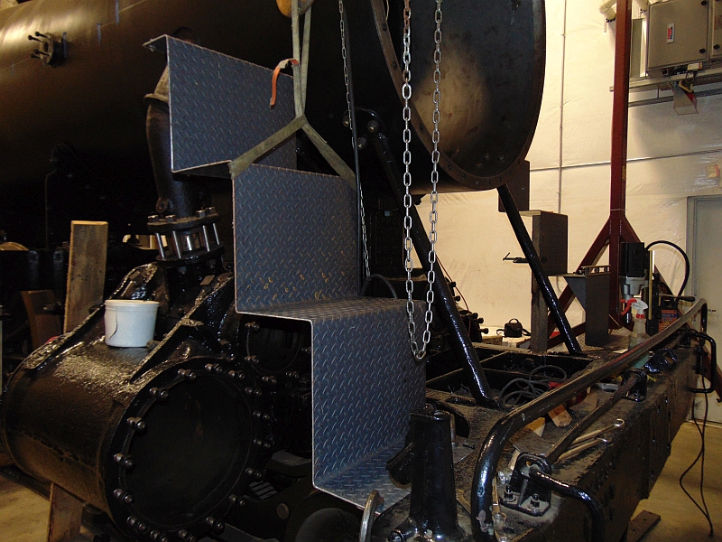
On the left side of the locomotive, the next parts added for fit-up include the steps over the air compressors and the rear portion of the runboard/cab floor.
Also, in place for fit-up is the lower cab wall that closes in the space between the runboard and the firing deck.
Moving to the right side of the locomotive the process is much the same except that at the forward edge of the cab the runboard is a bit higher off the rail than on the left side.
The rest of the right side is much simpler in that it is a single level. The forward runboard brackets here, too serve as brackets for one of the main air reservoirs.
The fit-up process is a work in progress but is moving us ever closer to the boiler hydrostatic test and then steam test.
As we work towards the completion of the Chicago & Northwestern 1385 steam locomotive rebuild, many things are in process. Currently, much of the work is focused on mounting and assembly. The Mid-Continent Railway Museum (MCRM) is excited to announce we have hired an additional locomotive specialist to support the work being done by SPEC Machine. MCRM has hired TJ Doyle. TJ comes with 20+ years of experience on locomotive rebuilding. He has worked for Kettle Moraine Railway and Mid-West Locomotive and Machine. TJ lives in the area and has winters off from his current career as an operating engineer. We look forward to his help and experience as we work to bring this project to completion.
Sometime after the first part of 1942, the C&NW changed the “face” of 1385. They were required to. The steps from the front bumper beam to the smokebox of the engine were changed to conform with a mandate from the Interstate Commerce Commission. The ICC was the federal board governing, amongst other things, the interstate dealings of the railroads from 1887 to 1996 and what was left of the ICC became the Surface Transportation Board thereafter. The range of the many things under their purview included safety appliances and devices on rail equipment and one of those things was the runboard steps on the front end of locomotives.
This update will be using “runboard” as that is the terminology the C&NW uses throughout their drawings for 1385, although the components are known by numerous other names, including running boards, foot boards, and tread plates. You will note the portion of the drawing below was issued January 12th, 1942, and elsewhere on a portion of the drawing not shown states “For all R-1 class engines with old boilers.” The 1385 is indeed an R-1 class and has what the C&NW called the old boiler.
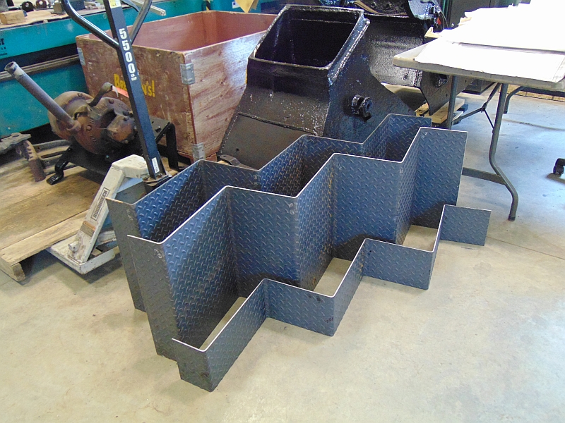
A best guess of the reasoning behind this requirement is that it made it so all vertical spaces between steps on the runboard would have a solid plate so a person’s foot could not slip between steps.
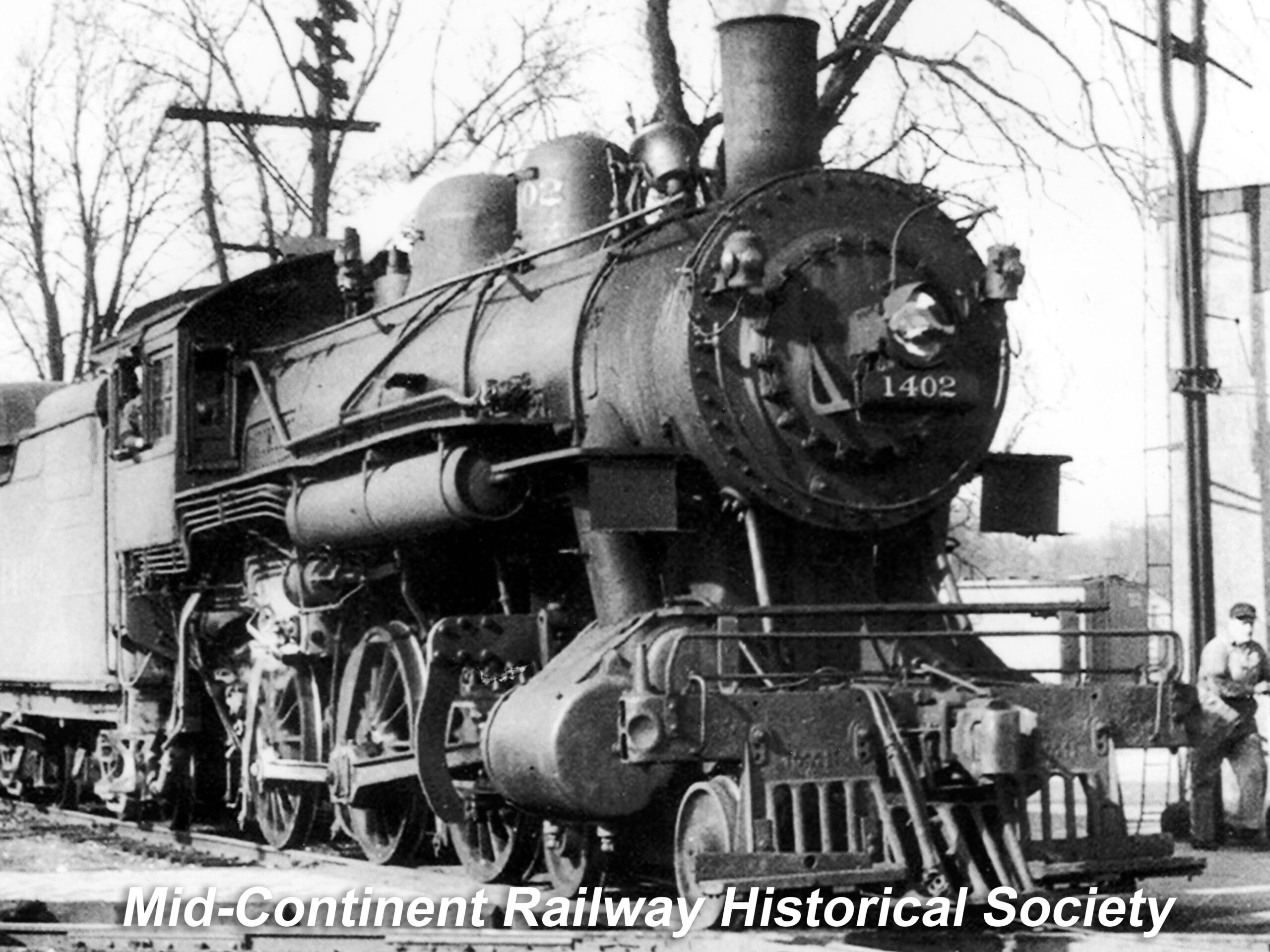
Here is a photo of sister engine C&NW #1402 showing one of the R-1 class step designs before the ICC required modifications.
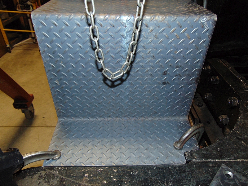
Below, we see the old steps propped up into place to be able to check alignment and attachment.
On the engineer’s side you can see how warped and cracked the attachment edge of the original step has become.
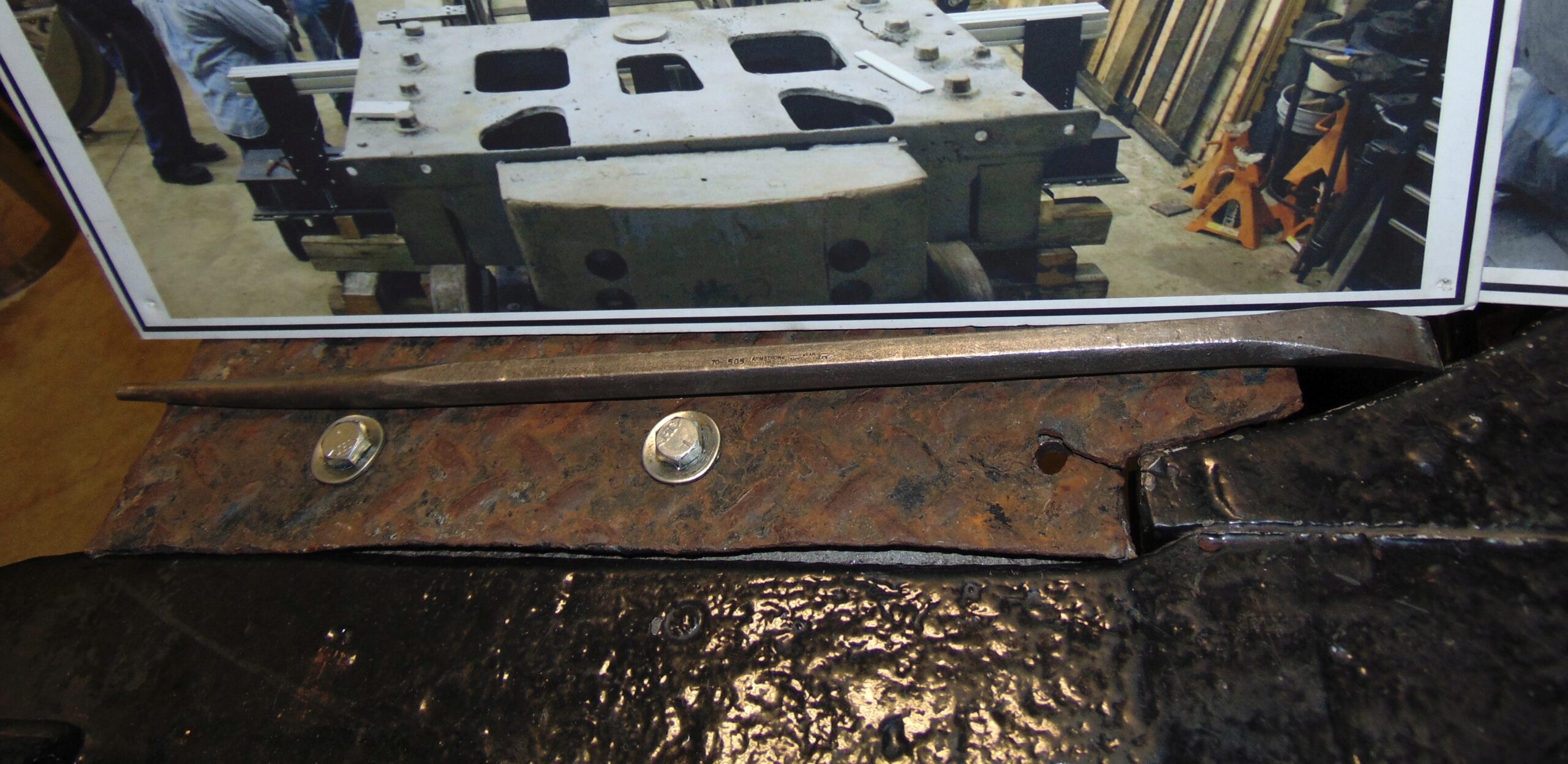
A new plate of steel was purchased, sheared, and bent to form the replacement steps.
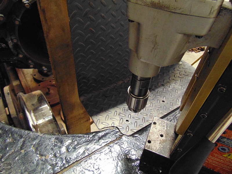
Here, we see the new engineer’s side step has been trimmed to fit the bumper beam and is clamped in place, ready to be drilled for the mounting bolts.
On the fireman’s side the magnetic base drill has already made the holes and the bottom mounting bolts are in place.
The runboards that get attached to the smokebox and connect to the steps discussed in this update will be the next pieces of the puzzle to receive attention.
Donate to the 1385 Restoration Fund
The Chicago & North Western #1385’s restoration relies heavily on donations. We’d love to bring this piece of history back home to Mid-Continent and have it running again. If you like seeing these updates and would like to help bring this project to fruition, please consider donating!