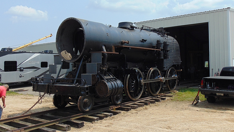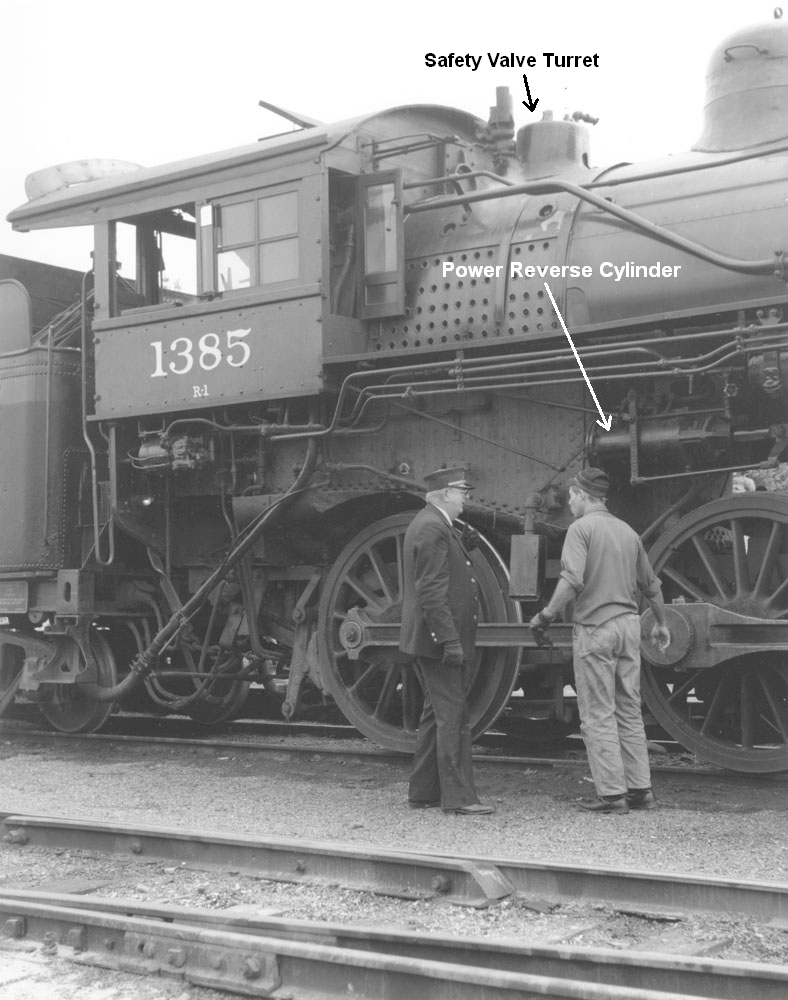
A few days ago, the #1385 felt her first sunshine with the new boiler, and now the boiler has received its first Wisconsin water.
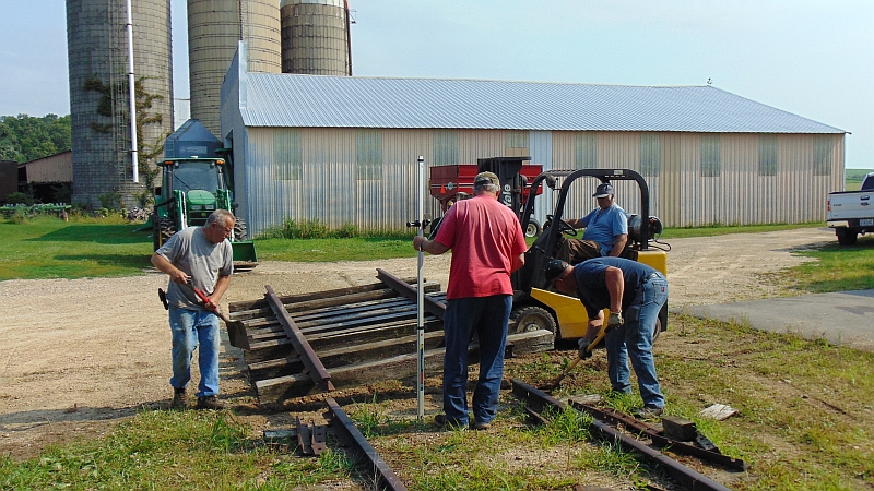
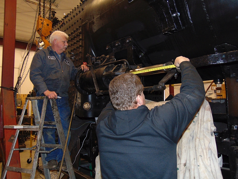
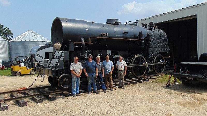
To clean up details from our last update, we have 2 crew photos because someone has to hold the camera. The first shot shows Gary A., General Foreman of Steam Ed R., Gary B., Richard P. and Spec Machine owner, Steve R.
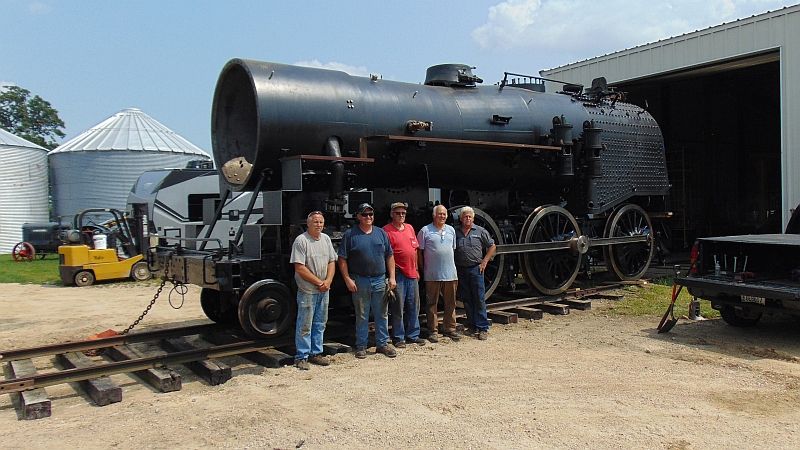
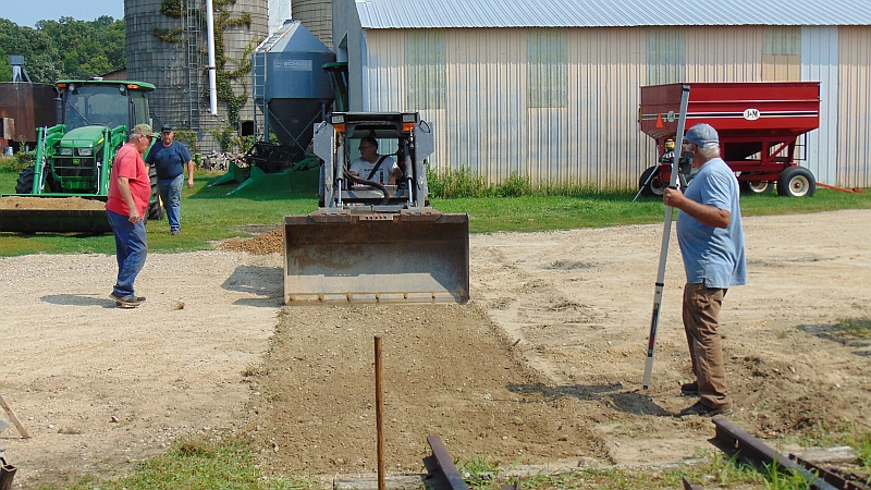
The second shot is Gary A., Ed R., Steve R., Richard and Roger F. Roger provided and operated some of the machines used to lay the track.
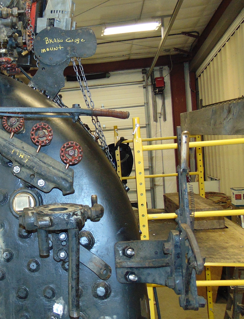
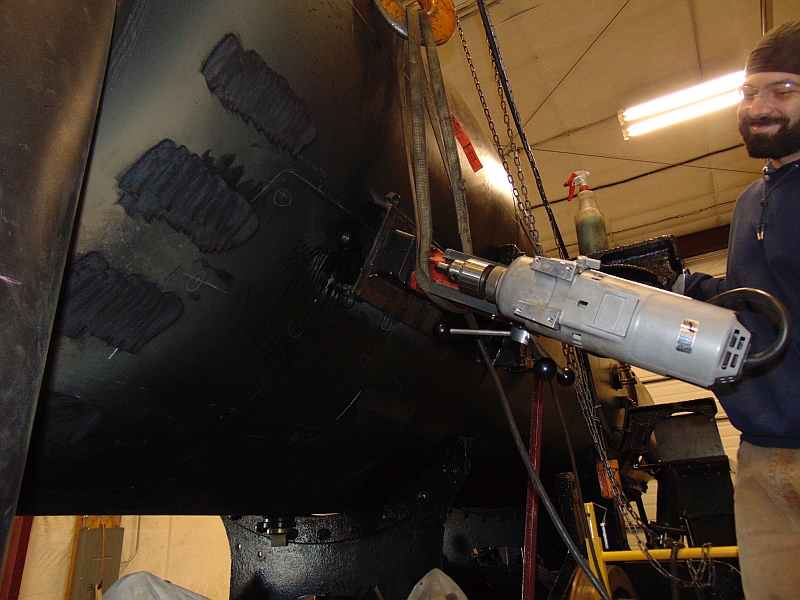
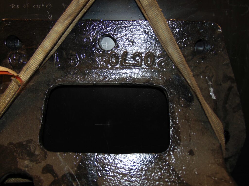
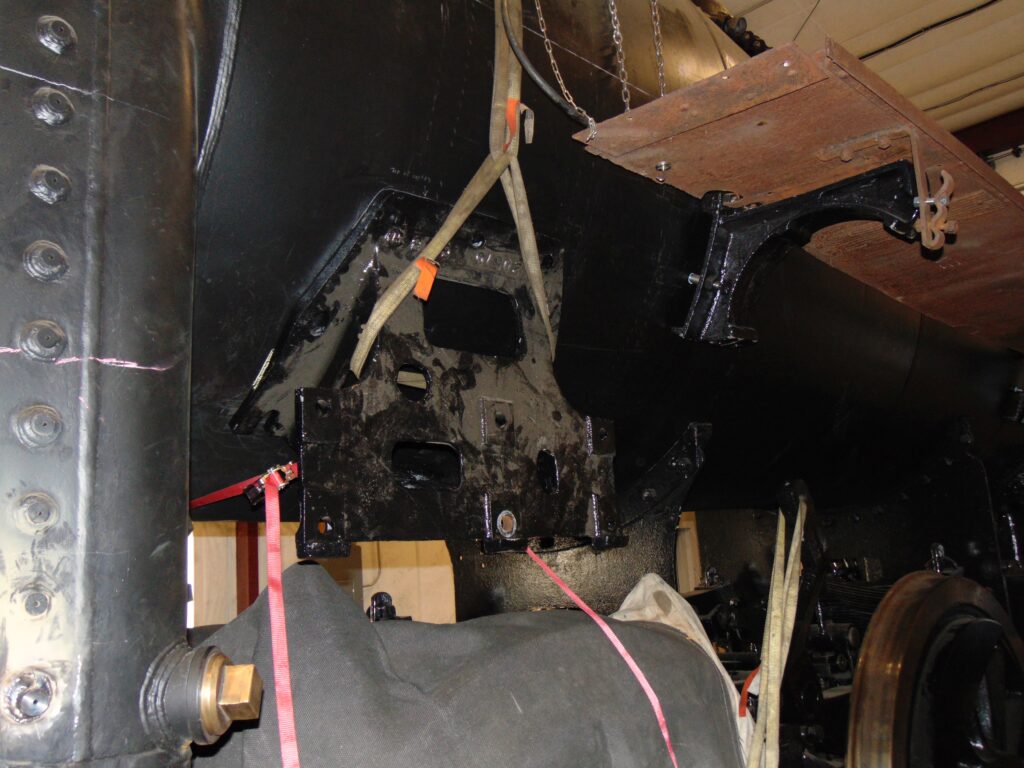
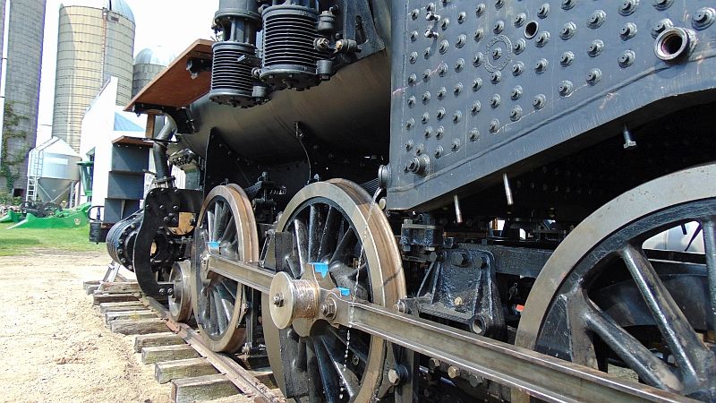
After all the work that has been done on the boiler, we need to flush it out before we can prepare for a pressure test. The first trickle coming from a firebox washout becomes a steady flow carrying debris from the stud installation with it.
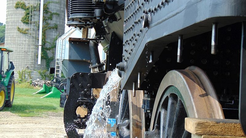
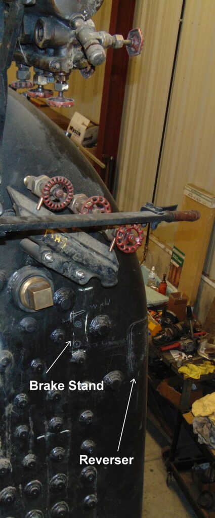
A large hose was used in the steam dome, then Ed switched to a smaller hose to flush from the washouts at the front end of the boiler.
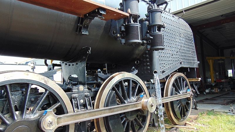
The engine seems to be saying, “Ahhhh,” while enjoying the afternoon sun and a nice, clean feeling.
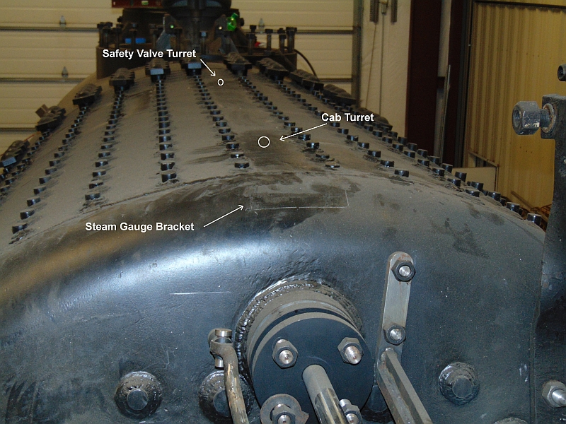
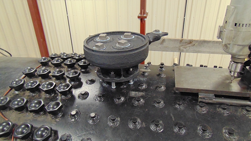
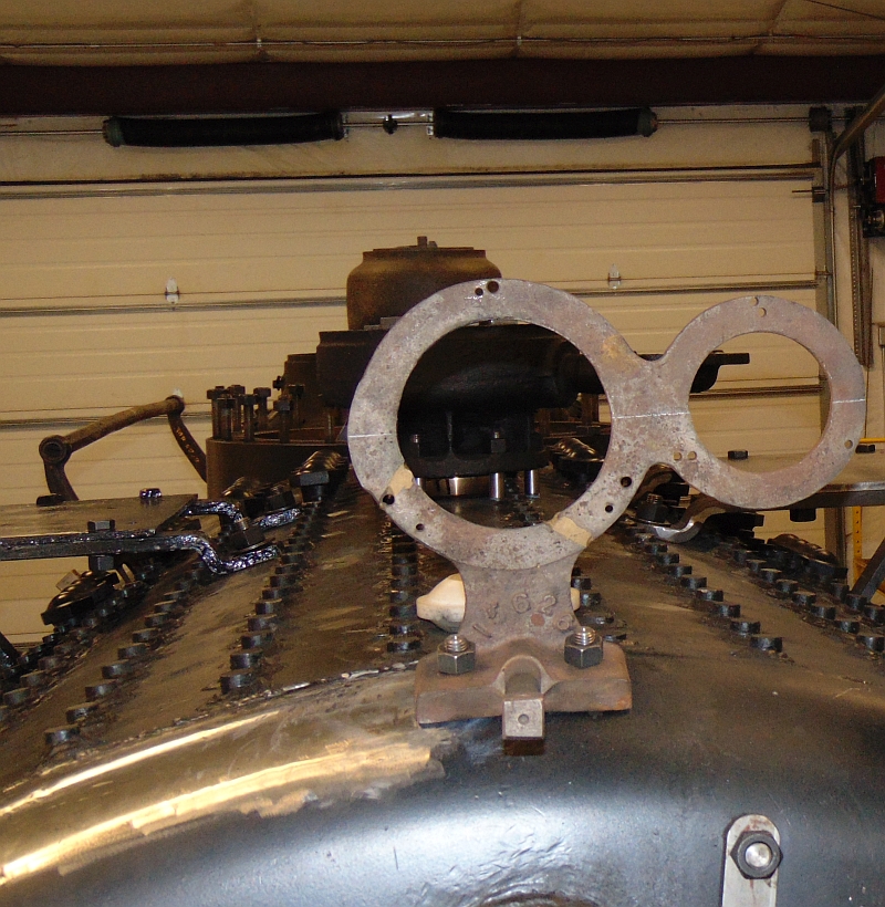
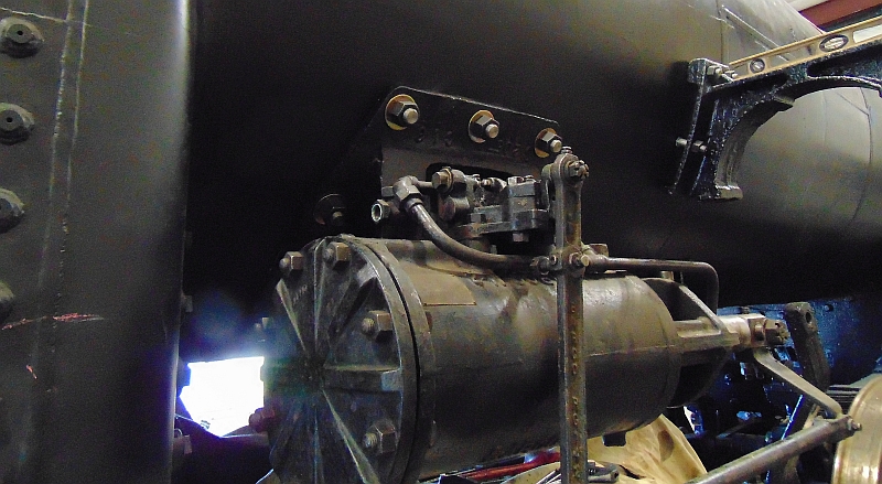
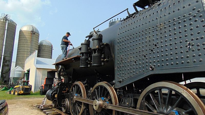
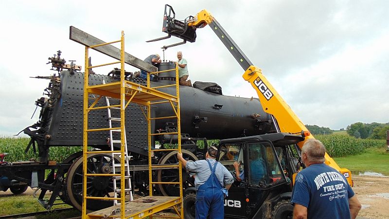
The next morning the steam dome was mounted on the boiler with help from Blue Star Farms who not only provided the water but also mechanical help.
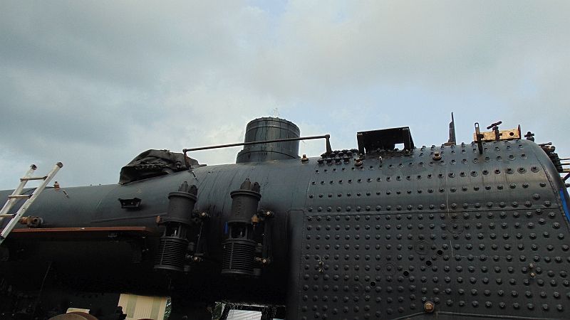
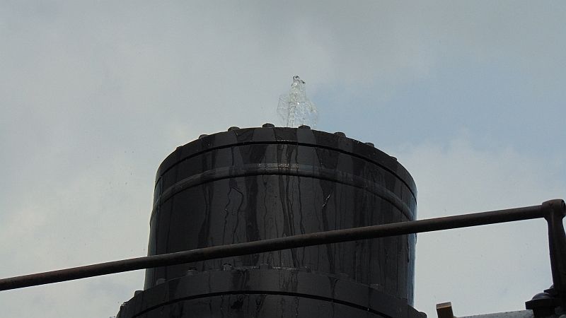
With the steam dome in place, the engine was filled. Approximately 2800 gallons later, the vent hole in the steam dome lid looked like a bubbler.
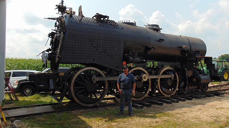
We have already identified a few minor weeps that will need attention and once the water is warmed to the proper testing range, we will pressurize the boiler to see if there are any further items for the “fix-it” list. Then the boiler will be drained & dried, the fix-it list addressed, and the boiler refilled and pressurized again to make sure everything was truly fixed. Once we know that we have a vessel that has no leaks, we can look to scheduling a test for the FRA.