What are the first three things an operator must know on any boiler? 1) Where’s your water?, 2) Where’s your water?, And 3) Where’s your water?
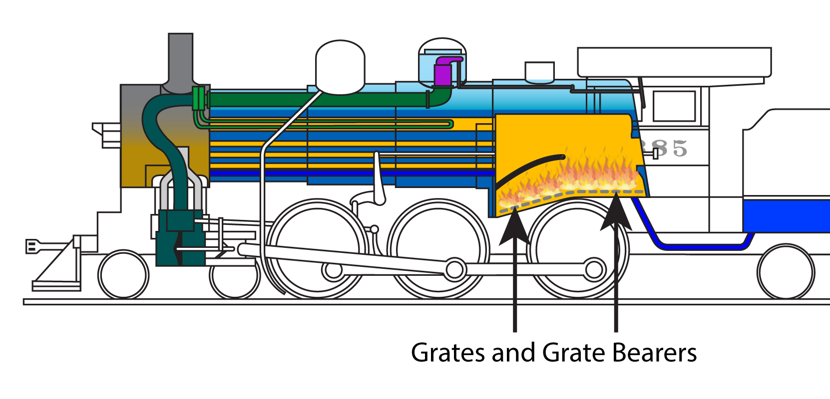
A steam locomotive’s water level is so important the Federal Railroad Administration includes an entire section dealing with water gauges in the CFR Title 49 Part 230 Steam Locomotive Inspection and Maintenance Standards. Part of 230.51 states that “…The lowest reading of the water glasses shall not be less than 3 inches above the highest part of the crownsheet. …”. What’s the crownsheet? It is the ‘roof’ of the firebox so it will have the heat of the fire on one side and the water of the boiler on the other.
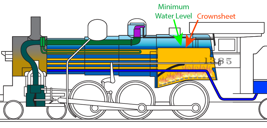
The water is constantly absorbing the heat transferred through the crownsheet and keeping the steel relatively ‘cool’. If the water were allowed to get low enough to let the crownsheet become dry then the heat of the fire from the underside could quickly damage the steel or worse.
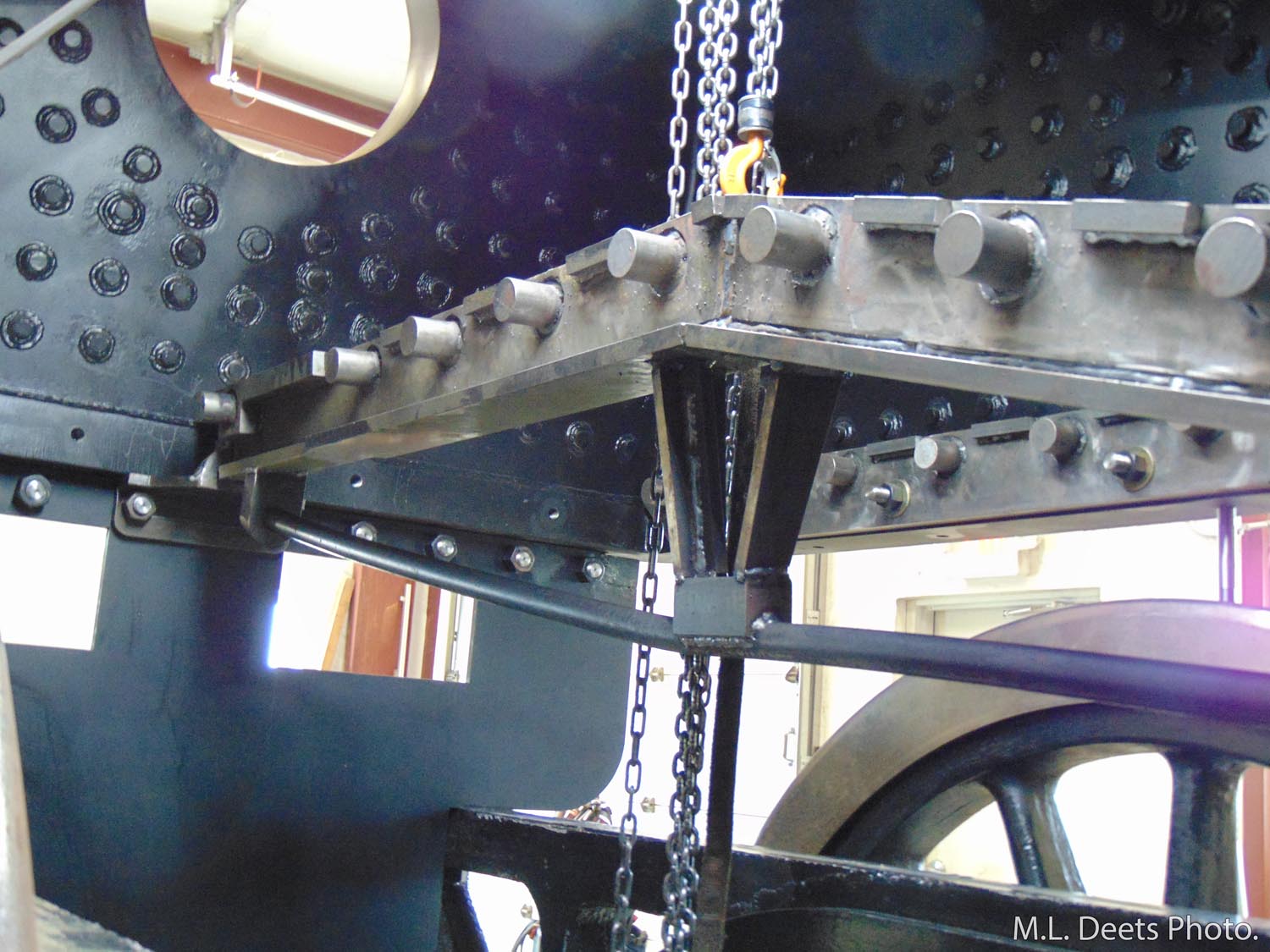
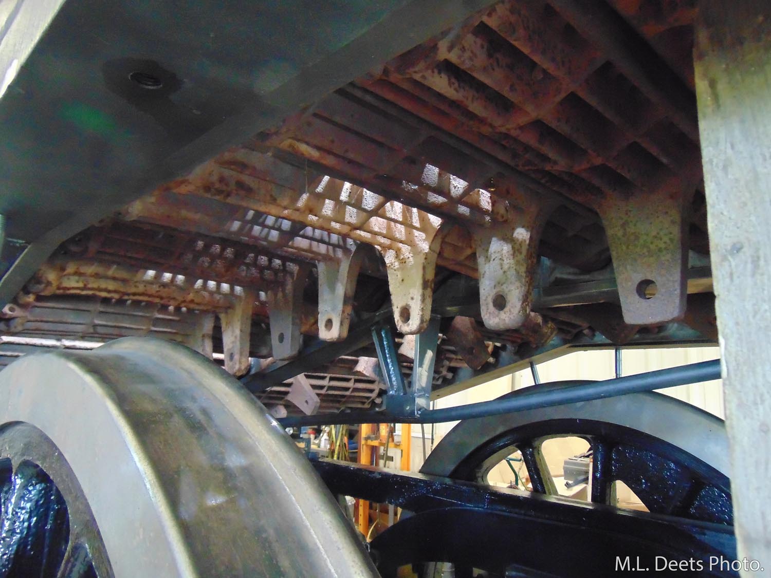
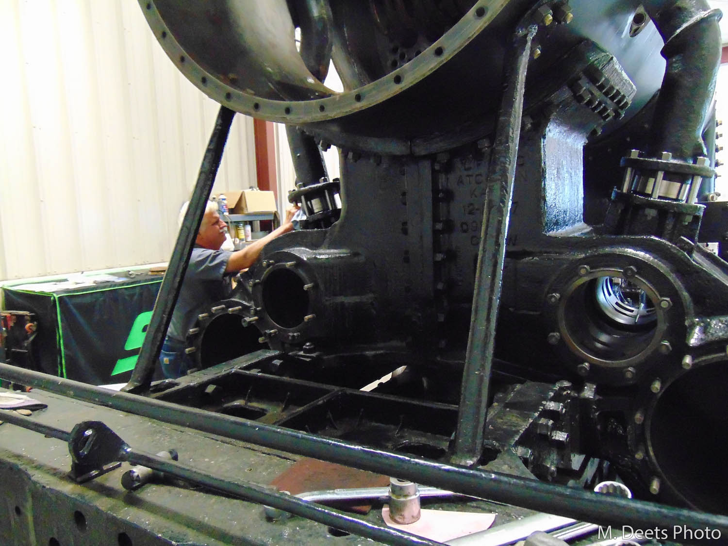
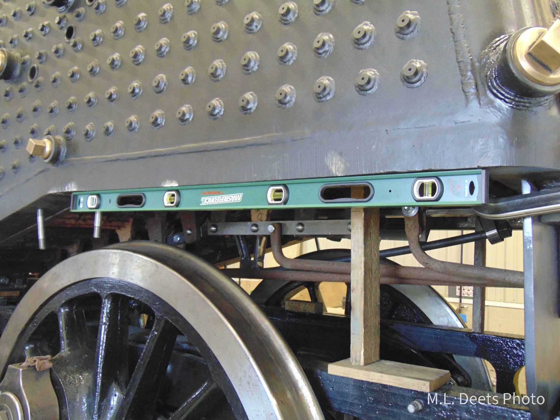
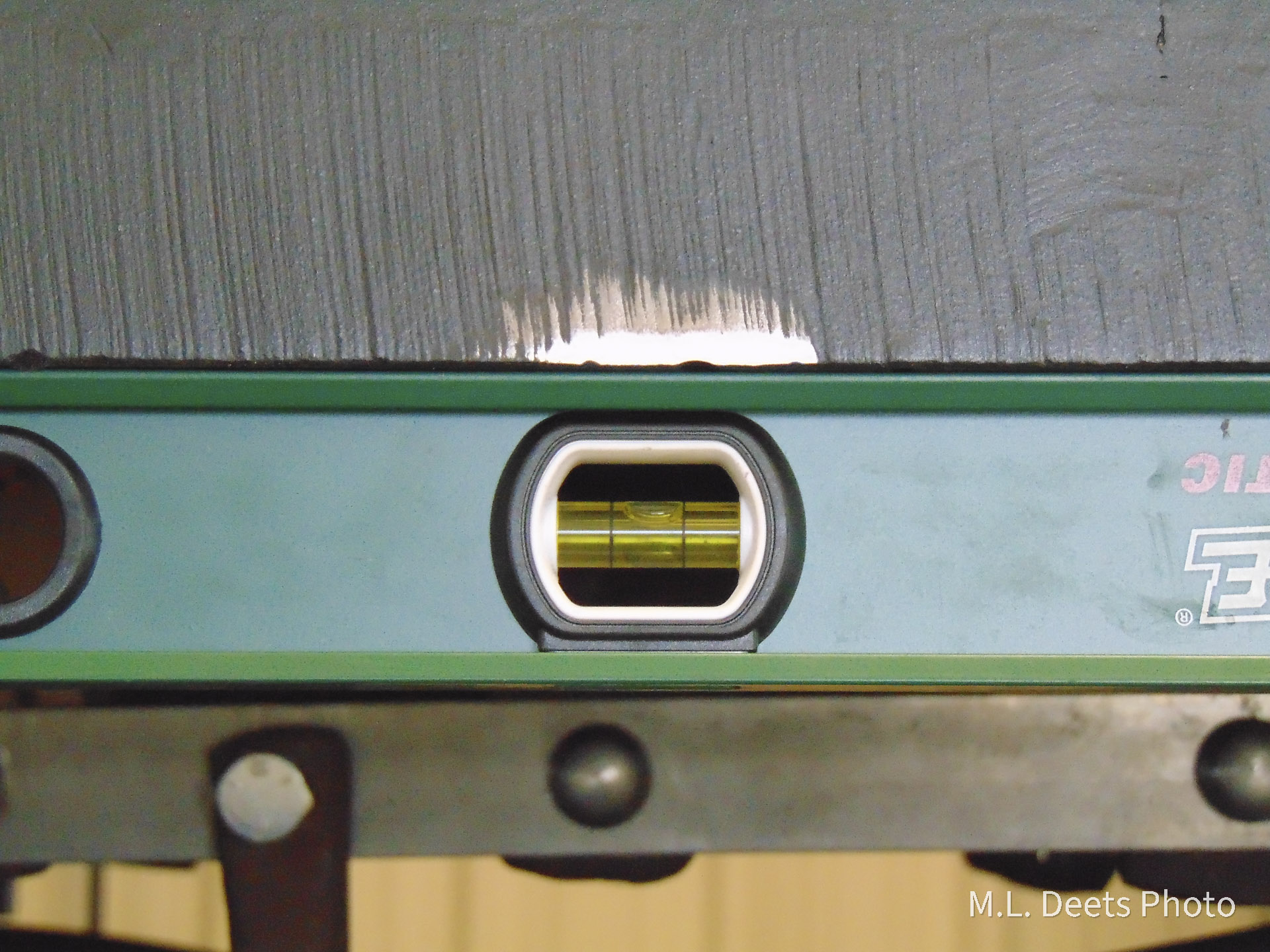
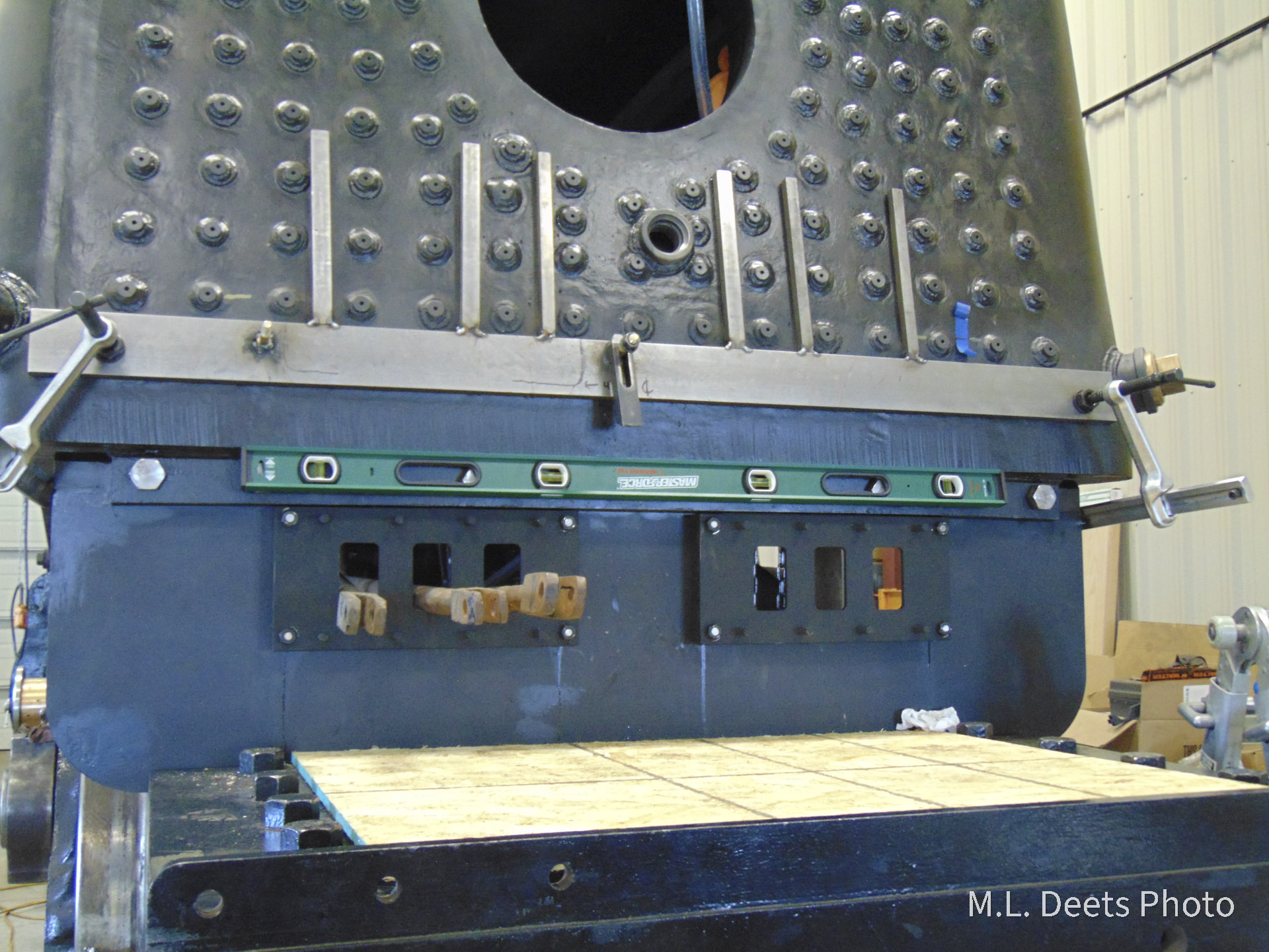
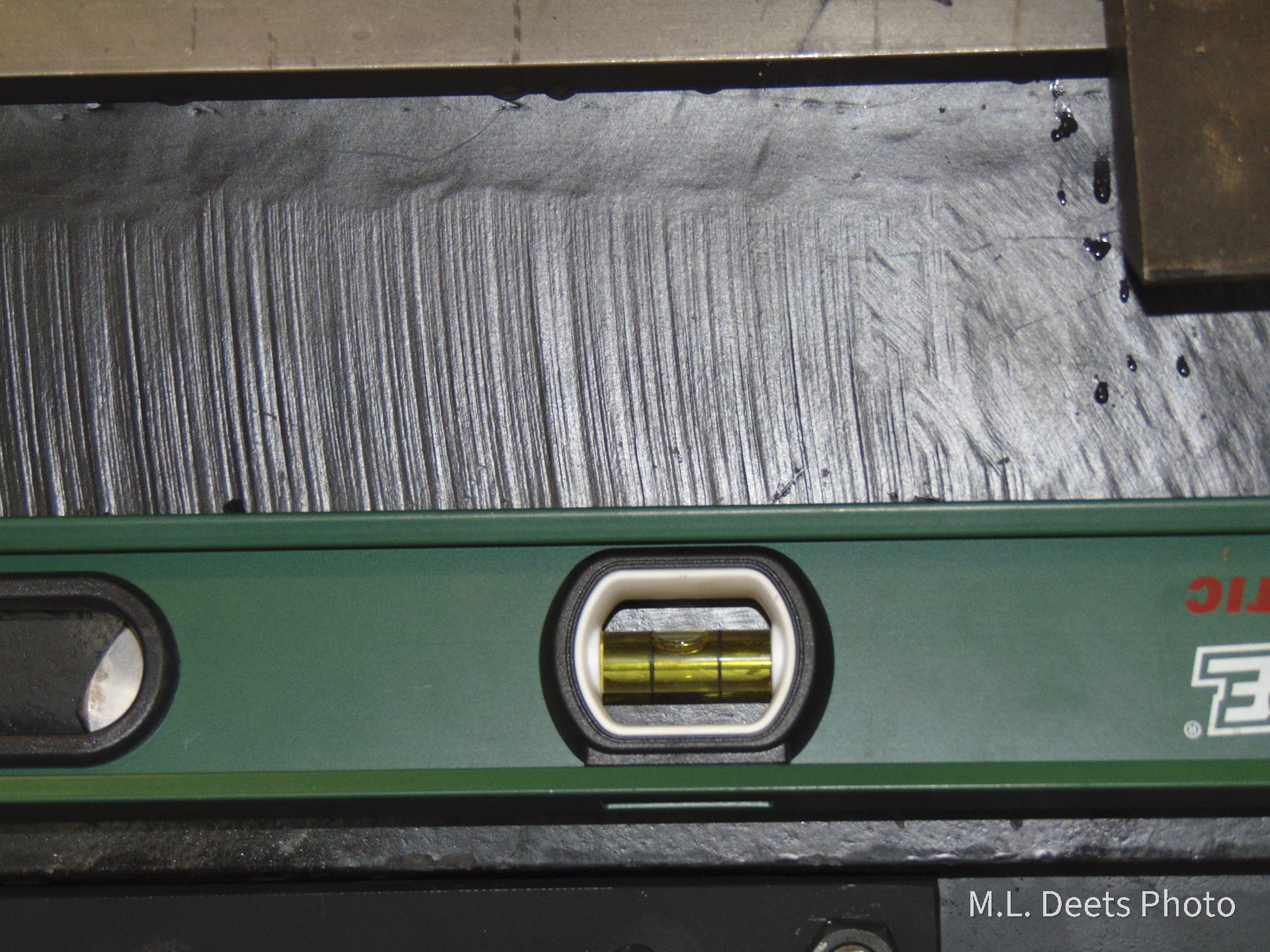
How do we prevent this situation? By constantly being aware of the water level in the boiler. But first we must know how low is too low by knowing where the top of the crownsheet is. This was done at SPEC Machine in January by first confirming the engine was setting level. Front to back level was first checked and then side to side.

Level under 1385’s firebox verifying front-to-back level. Closeup of side line level. Second level to check side-to-side level under backhead. Closeup of rear line level.
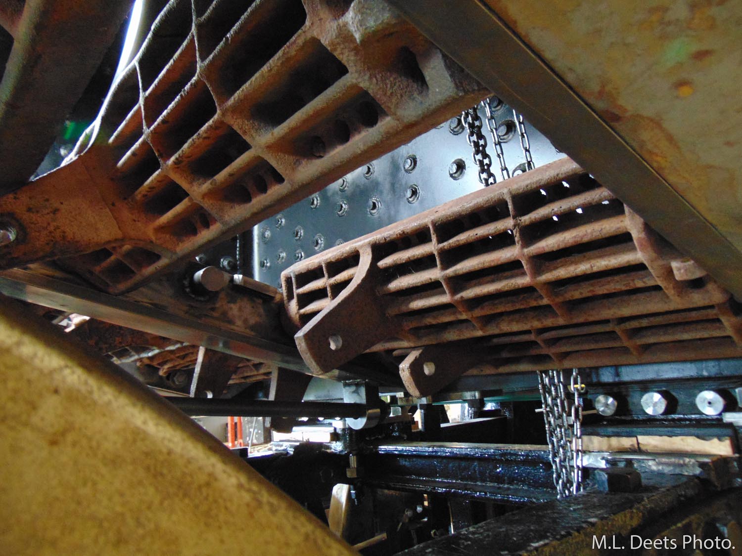
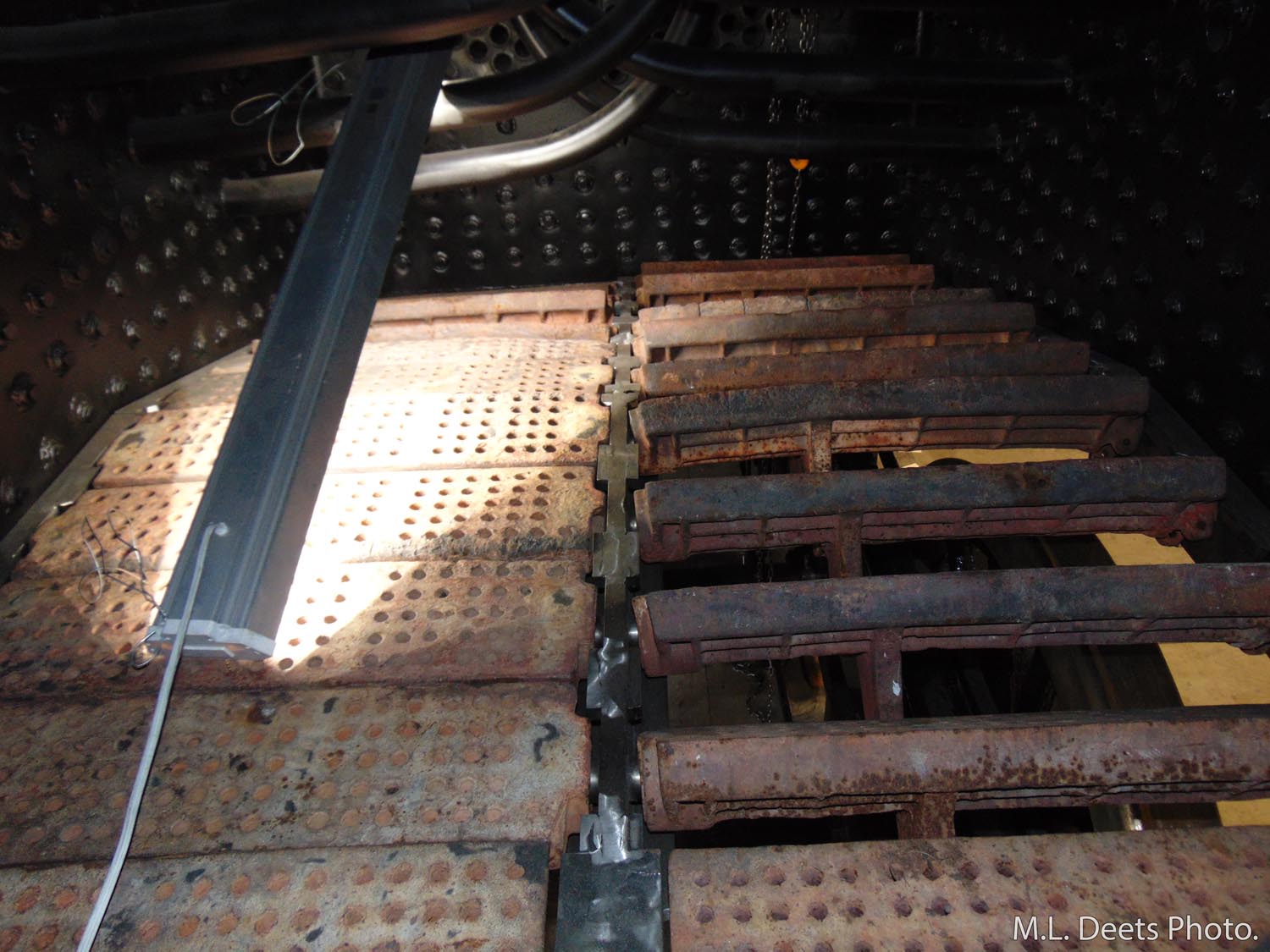
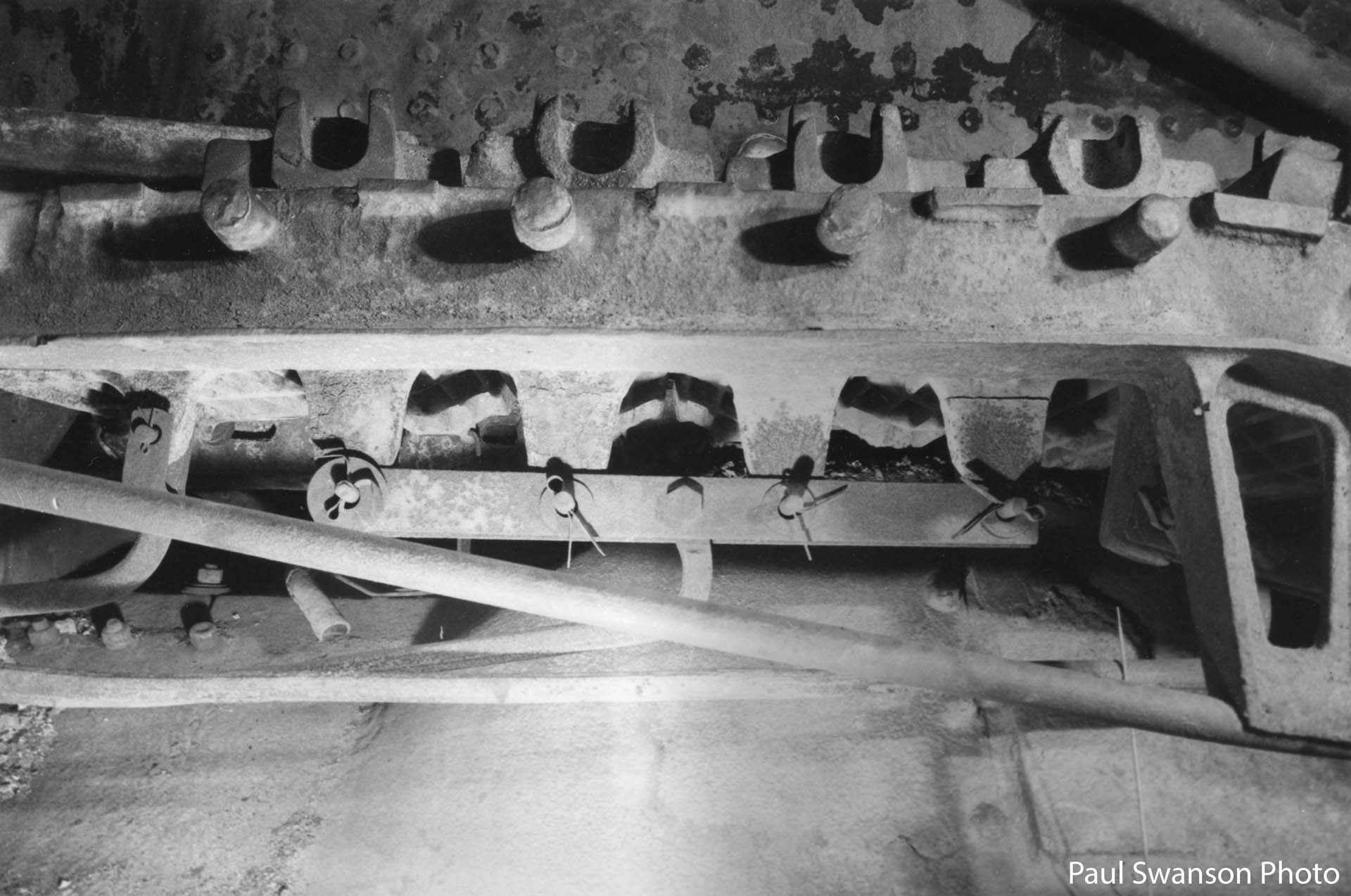
The next task was to use clear plastic tubing to create a “U” shaped tube open at both ends. One end of the tube was placed against the highest point of the crownsheet inside the firebox but with a small notch in the end to allow air and excess water to escape.
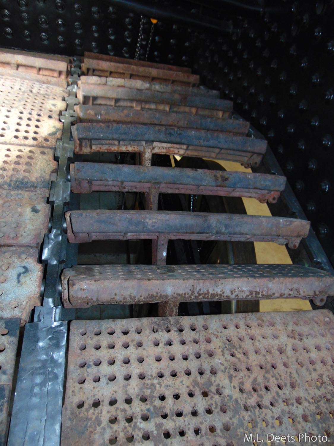
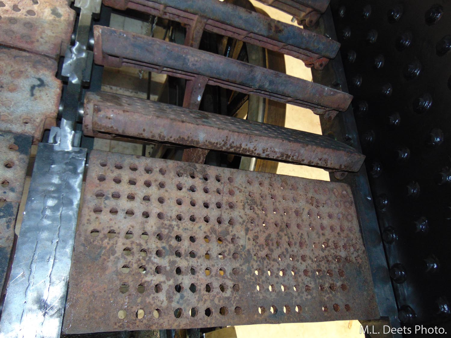
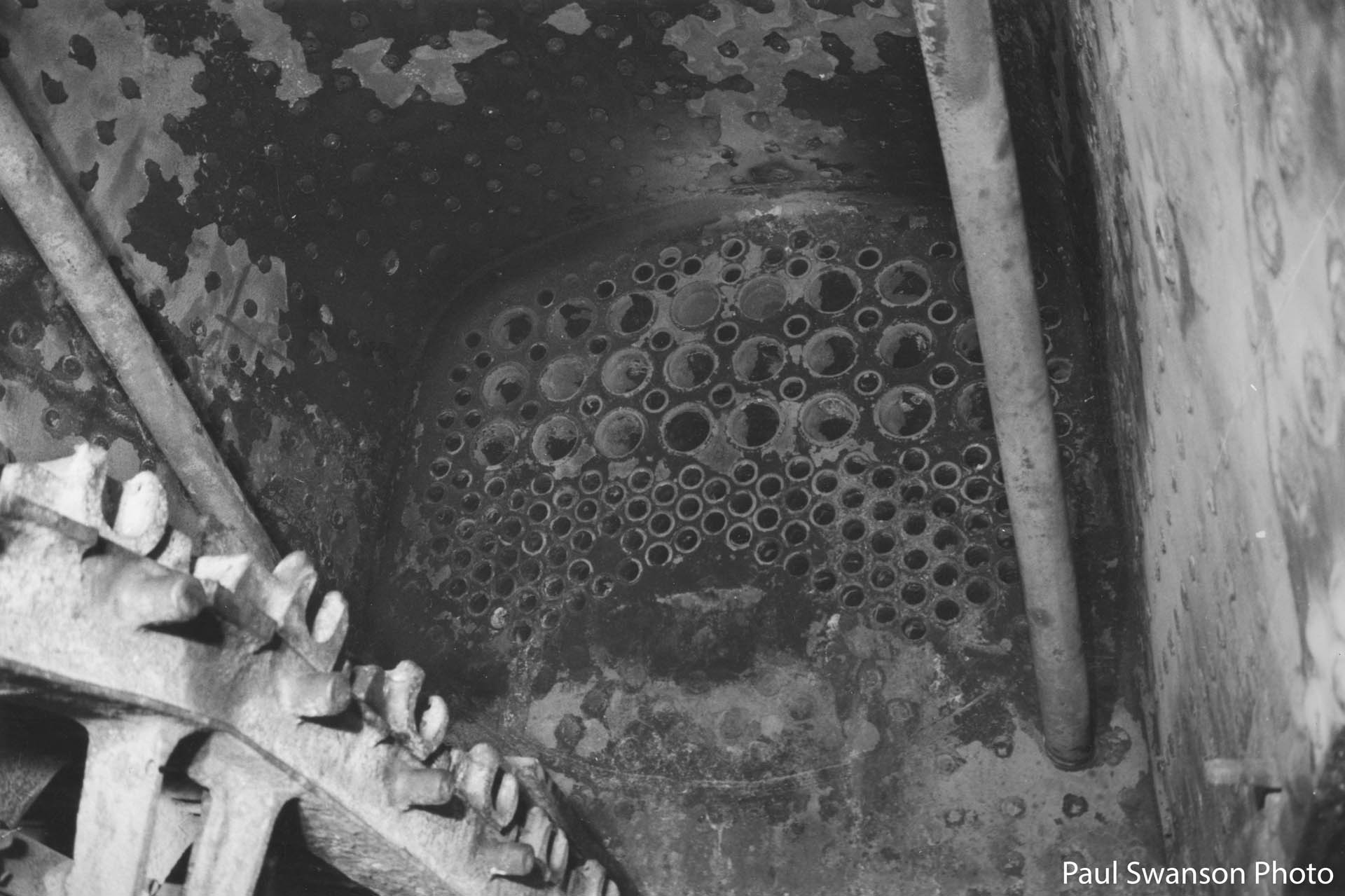
Water-filled tube inside firebox as seen from firedoor. Closer view of water-filled tube inside firebox. Note the superheater units visible within the flues.
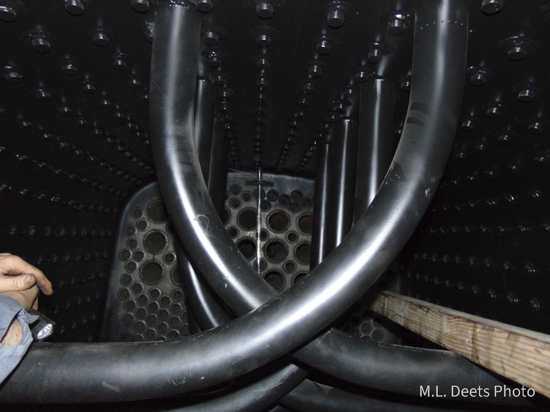
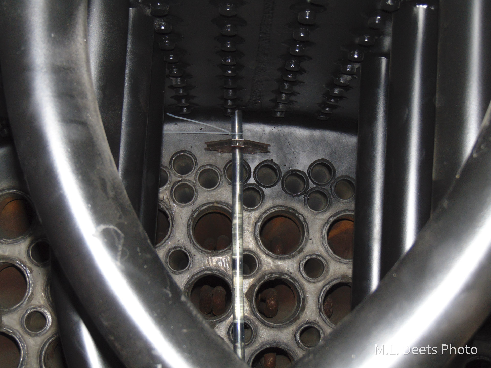
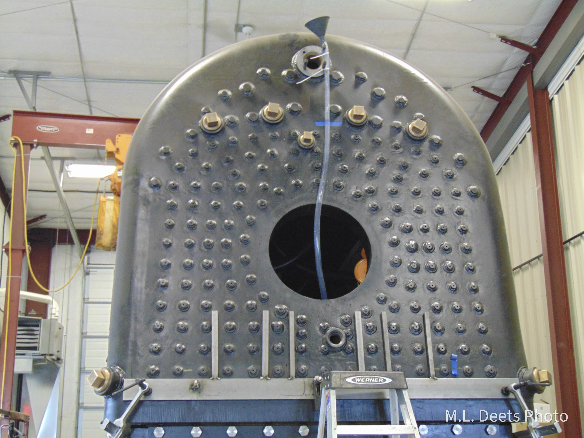
The other end of the tube was brought out through the firedoor and tied to the throttle gland so the outside end would be higher than the end inside the firebox and a funnel was used to fill it with water. Once the water quit running out of the end of tube in the firebox the level of the water shown at the outside end is equal to the level of the bottom or inside/fireside surface of the crownsheet.
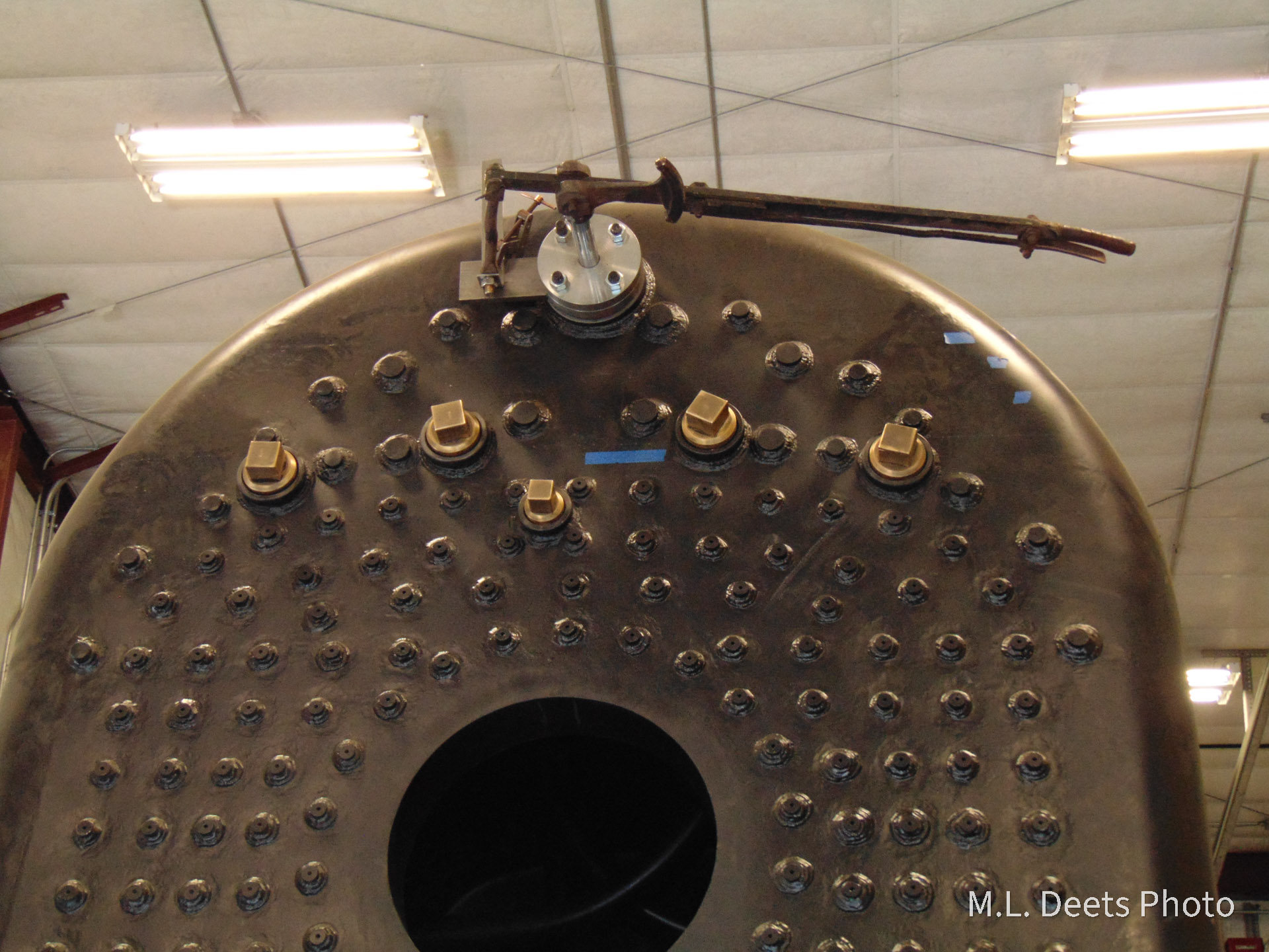
Water-filled tube coming out of firedoor and attached to backhead. Masking tape line marking the height of the bottom, or “fire side” of the crownsheet.

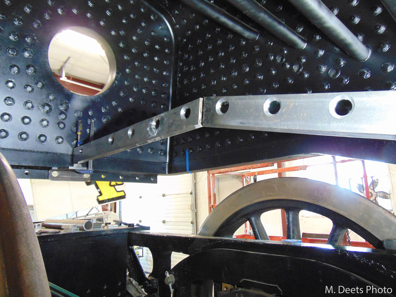
To locate the top of the crownsheet and mark it per FRA requirements we had to add the thickness of the welds and the crownsheet itself. Now that we’ve found the top of the crownsheet the water glasses and try cocks can be laid out for installation so the lowest water indication is no less than 3 inches above it. Generally speaking as long as we can see water in the gauges we’ll have at least 3 inches of water over the crownsheet if we’re on level track.
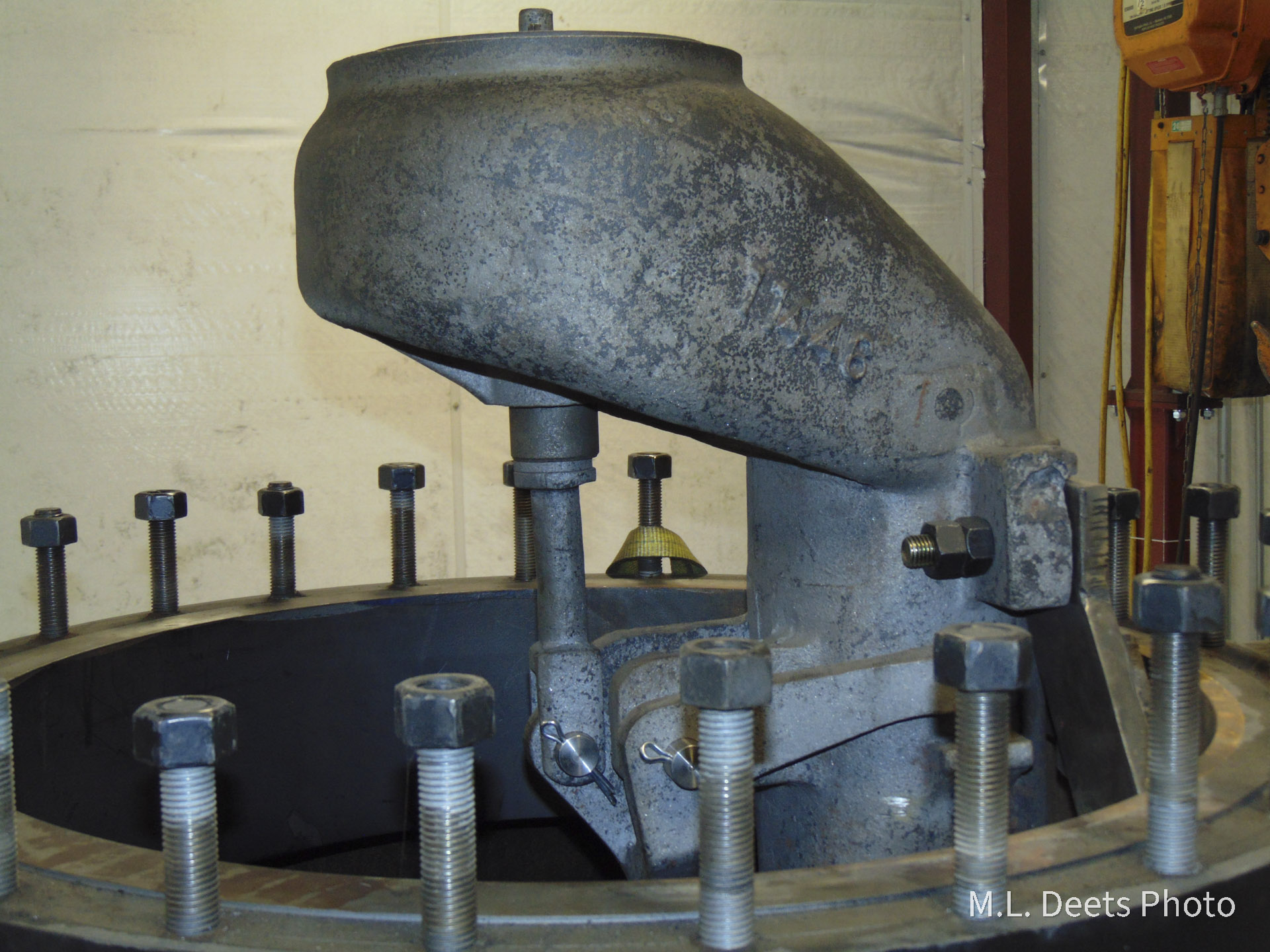
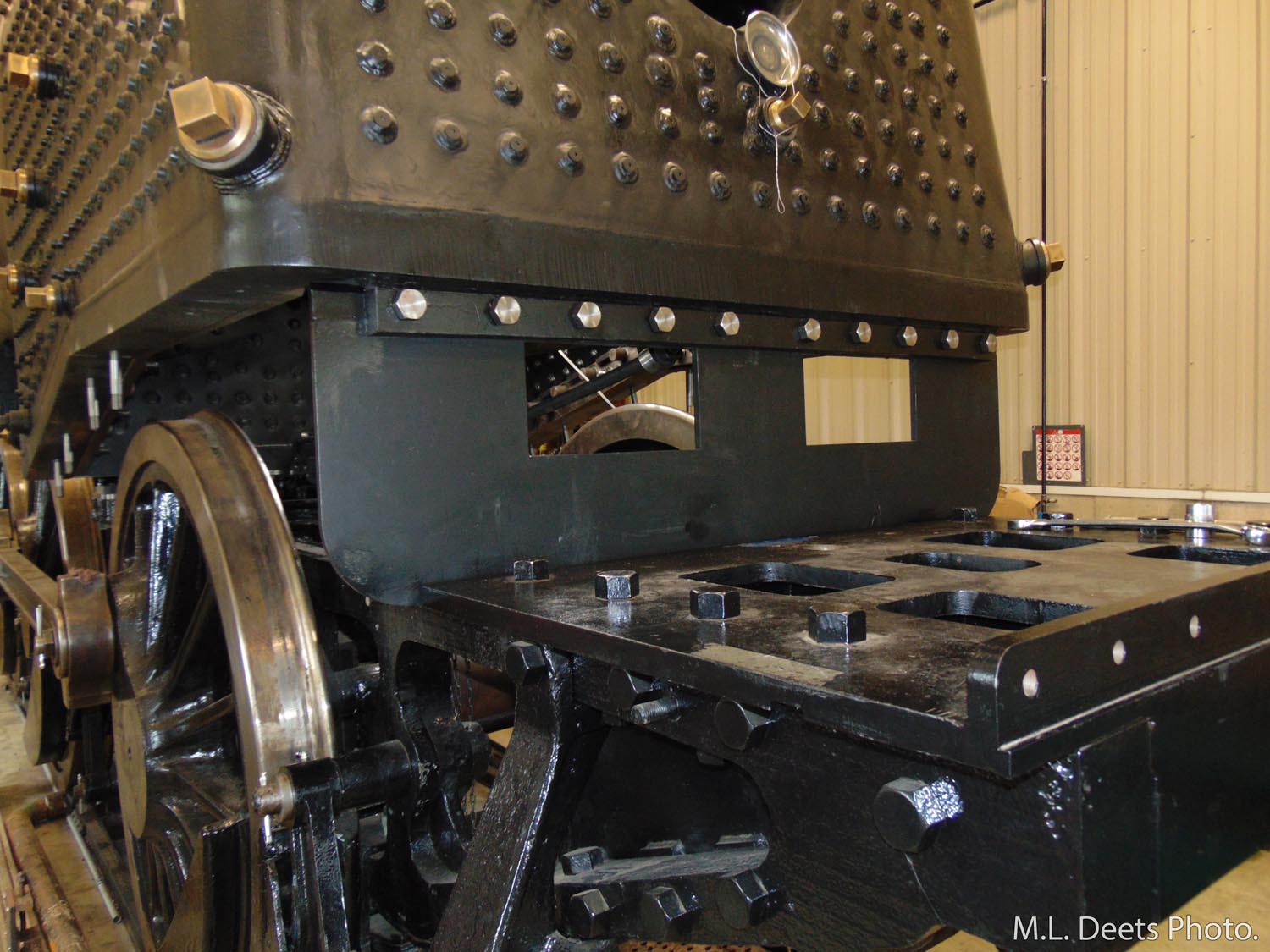
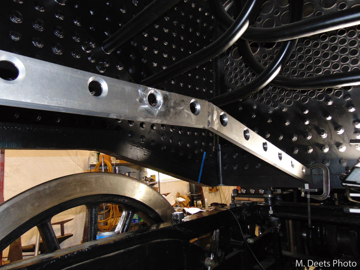
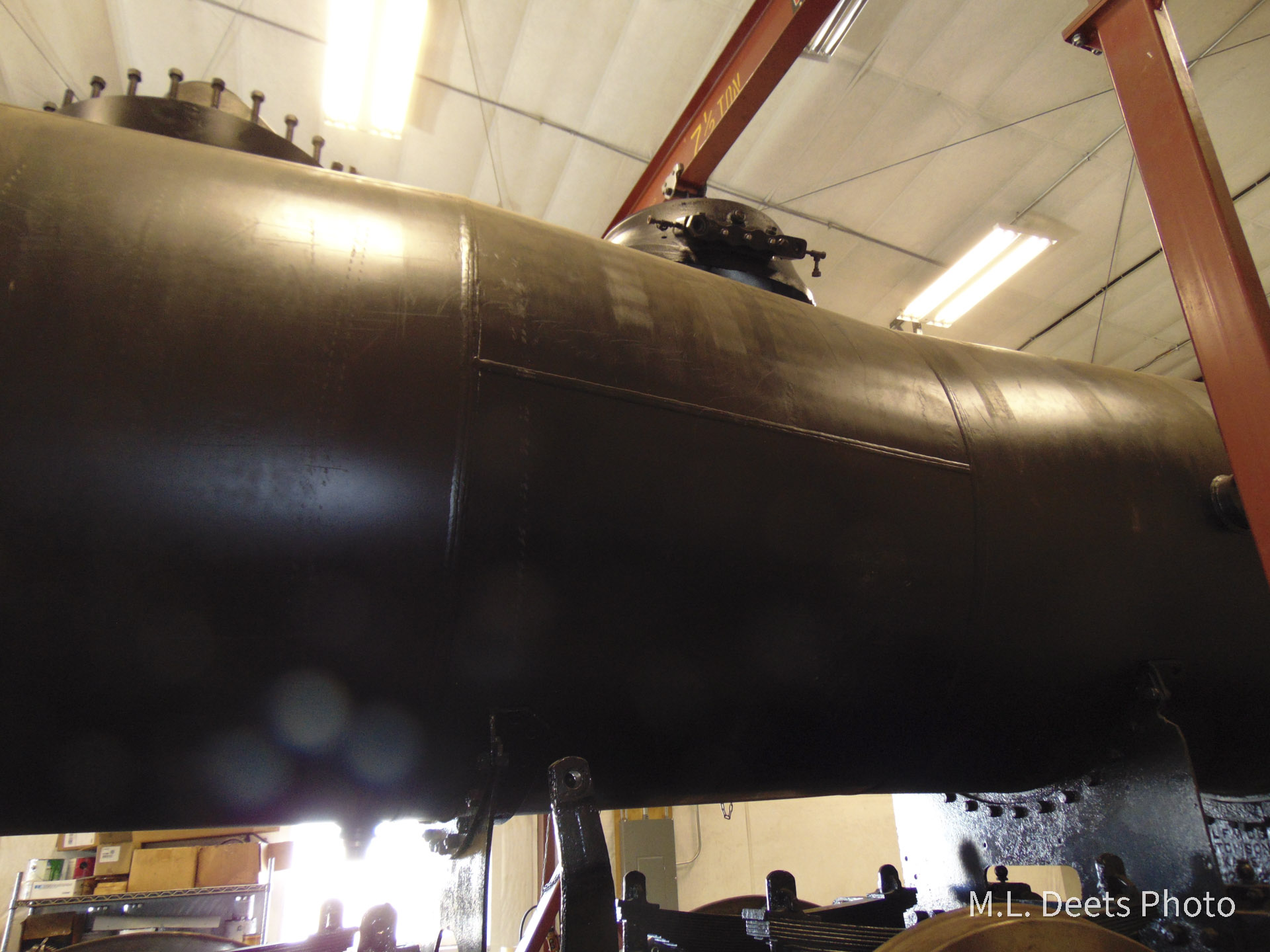
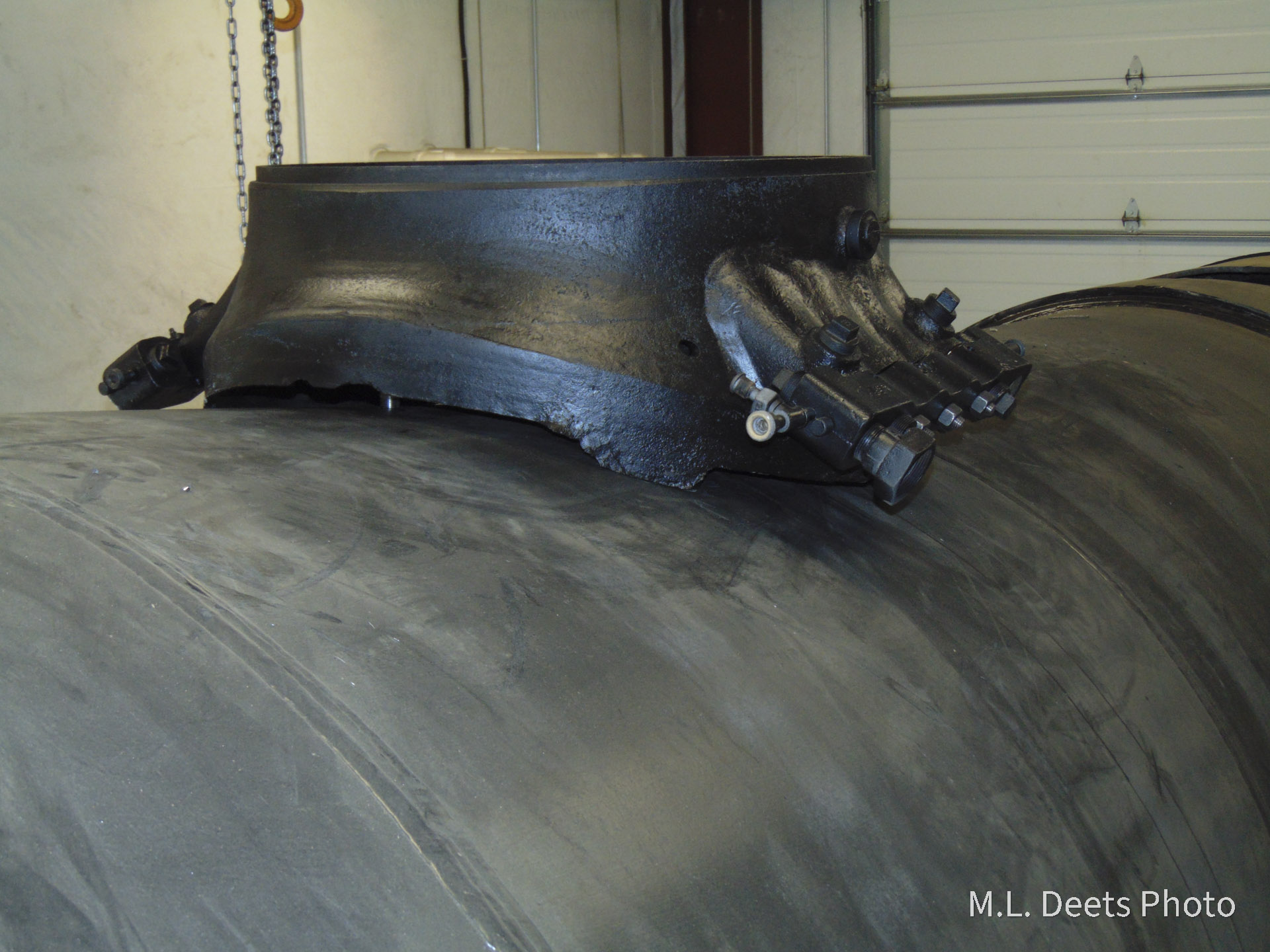
Once finished playing in the water, other layout and installation steps have been made. Locating and installation of the sand dome base has been finished and this task includes another milestone in the 1385 project; the first studs to be applied to the boiler since its delivery to SPEC Machine are used to hold the sand dome base in place. You can even see the glint of one of the new studs at the top of the boiler and just under the edge of the base here.
Lookup up at the sand dome from floor level. Installed sand dome. One of the new studs is visible.
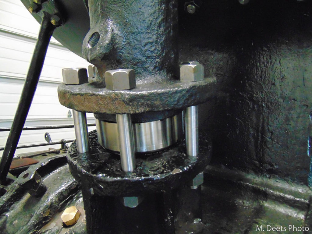
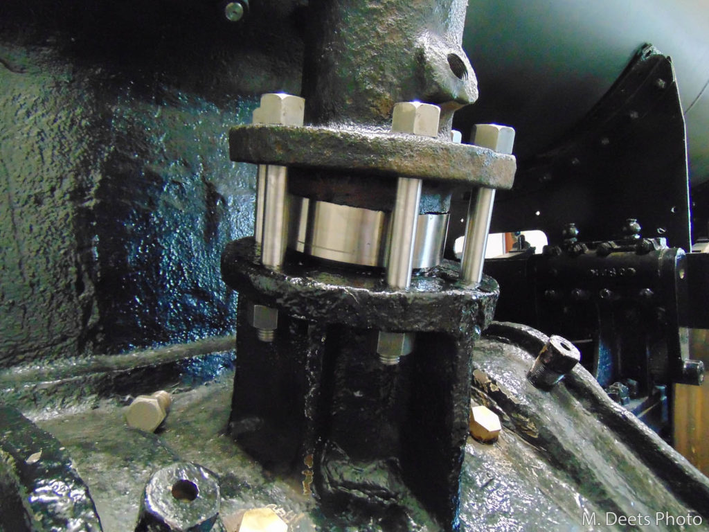
Another fixture on the backhead is the throttle lever and the pivot point that is studded to the boiler. Here Steve has rigged a temporary way to support the pivot to facilitate this layout. The throttle rod reaches through the packing gland attached to the backhead and through the boiler to connect with the bell crank and levers that will allow the engineer to open and close the throttle which resides in the steam dome.
Throttle lever attached to backhead. 1385’s throttle, located inside the steam dome.