With January coming to a close it is time to check in again with Chicago & North Western #1385’s progress. Steve Pahl, MCRM General Foreman of Steam, provided the following list of work being performed or recently completed as of January 20, 2021.
Key areas of work on C&NW #1385 during January 2021.
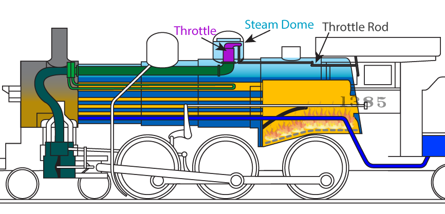
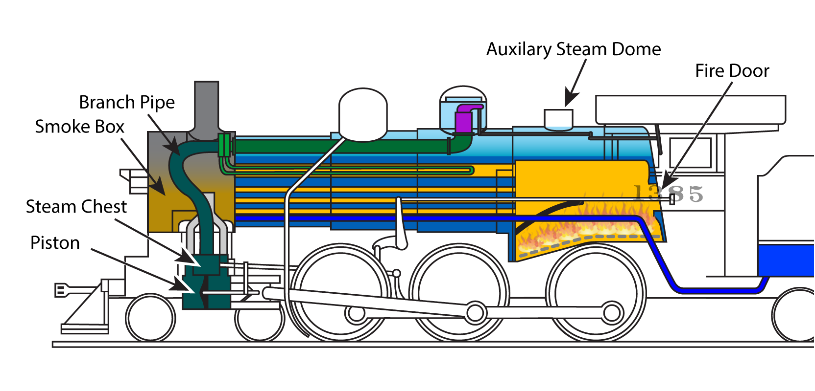
- The auxiliary steam dome is currently being repaired. The auxiliary steam dome is where the safety valves, boiler vent valve, and whistle are mounted. The boiler vent valve is used for filling the boiler with water and serves as a vent when draining said boiler. The whistle, of course, is the epitome of steam railroading!
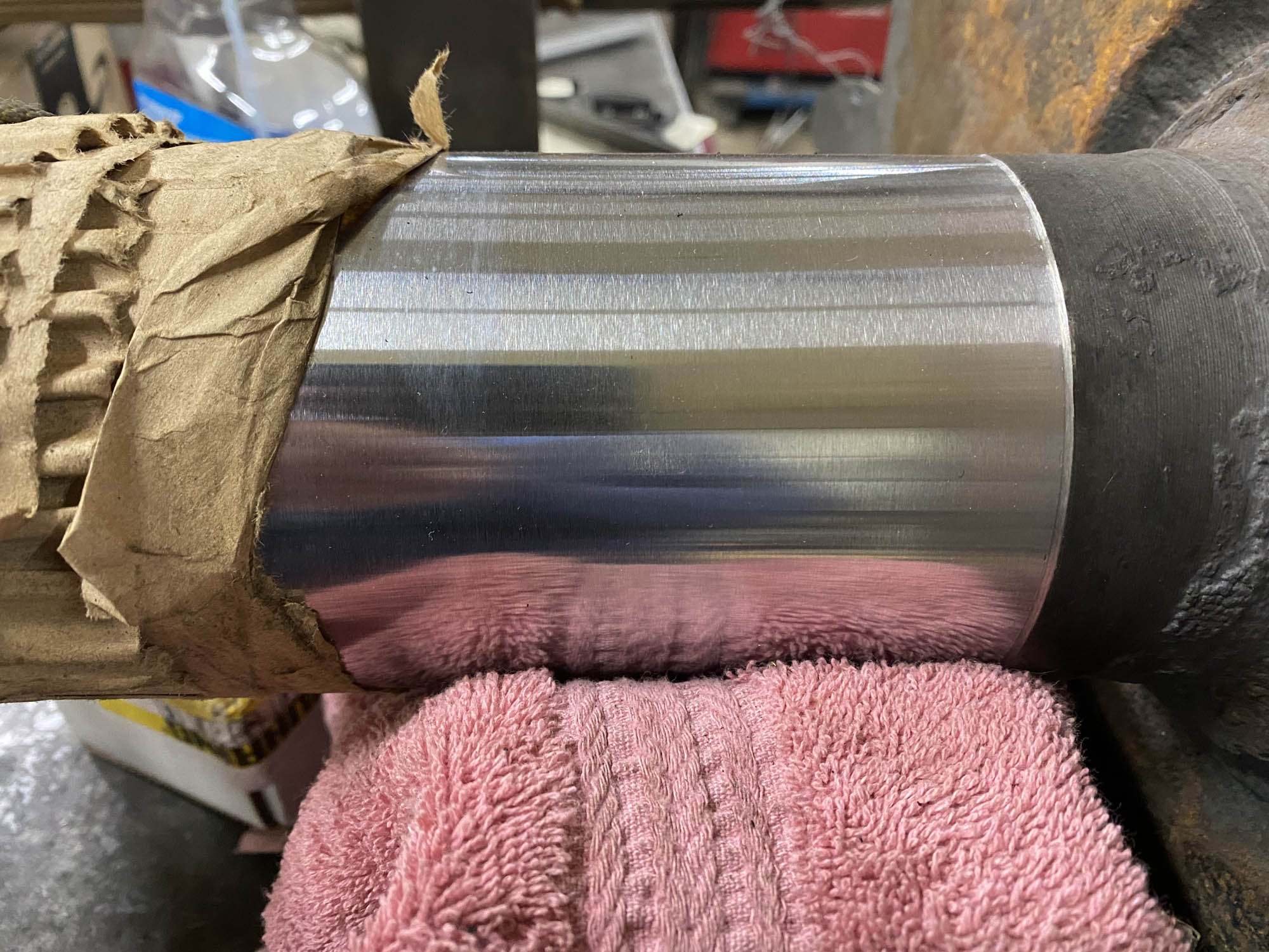
- The cast iron blanks for the new piston bull rings have been water jet cut to rough dimensions and are ready to be machined to the final dimension with grooves cut for the piston rings. The center “donut hole” left over after the piston bull rings were cut out are being used as the blanks for the two smaller bull rings that are needed for each valve. That way there is not nearly as much waste in material lost.
-

- Two cast iron blanks which will become C&NW #1385’s piston and valve bull rings. M.L. Deets photo.
-
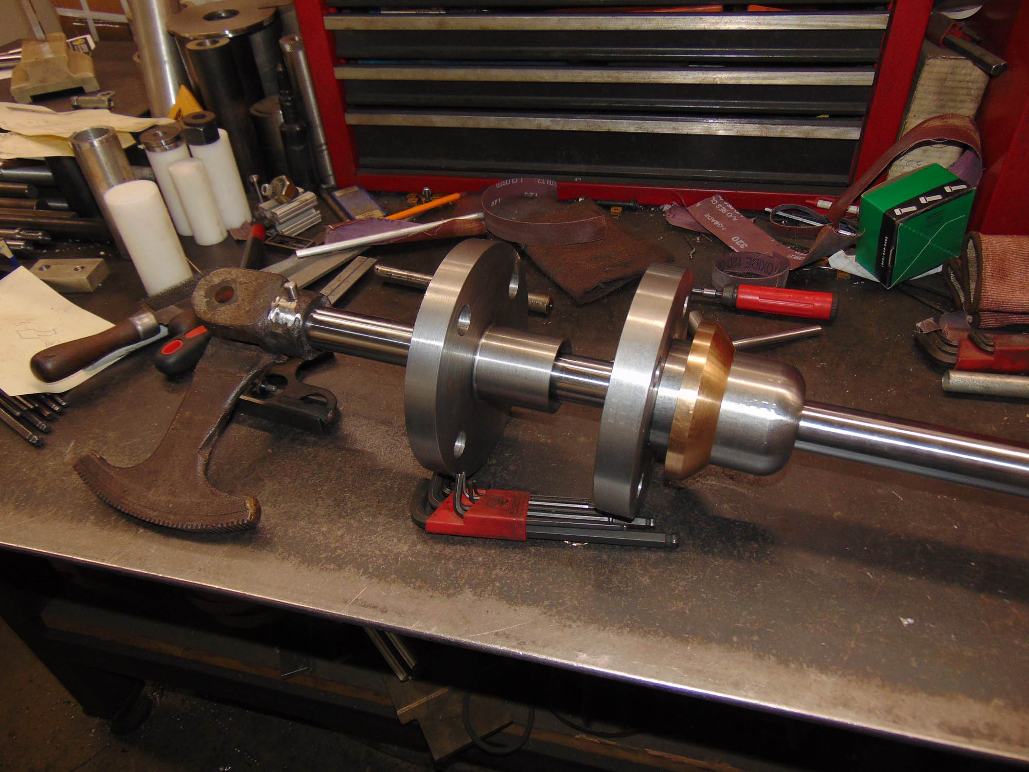
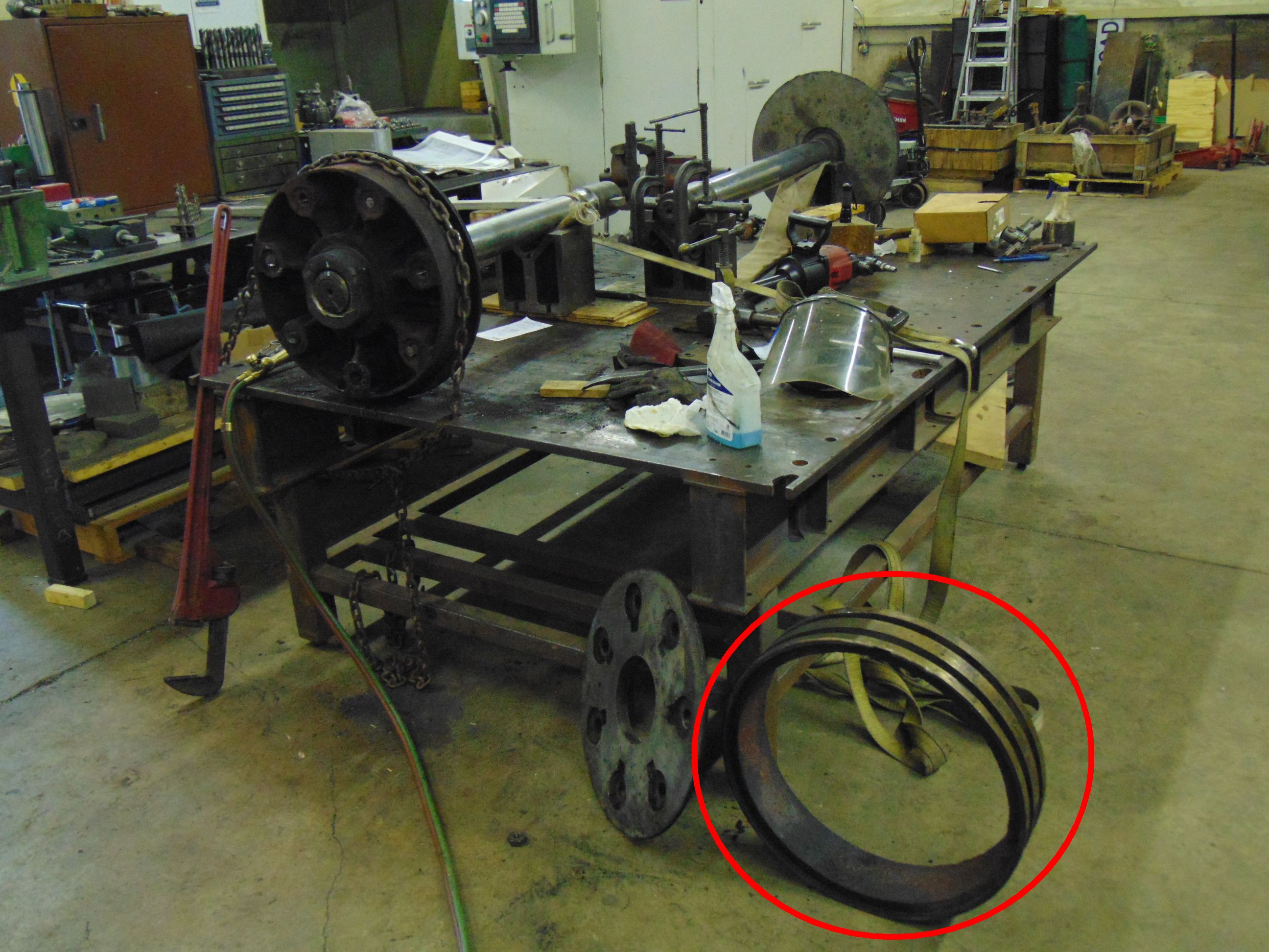
- This photo from February 2017 shows 1385’s disassembled piston. One of the bull rings is circled. M.L. Deets photo.

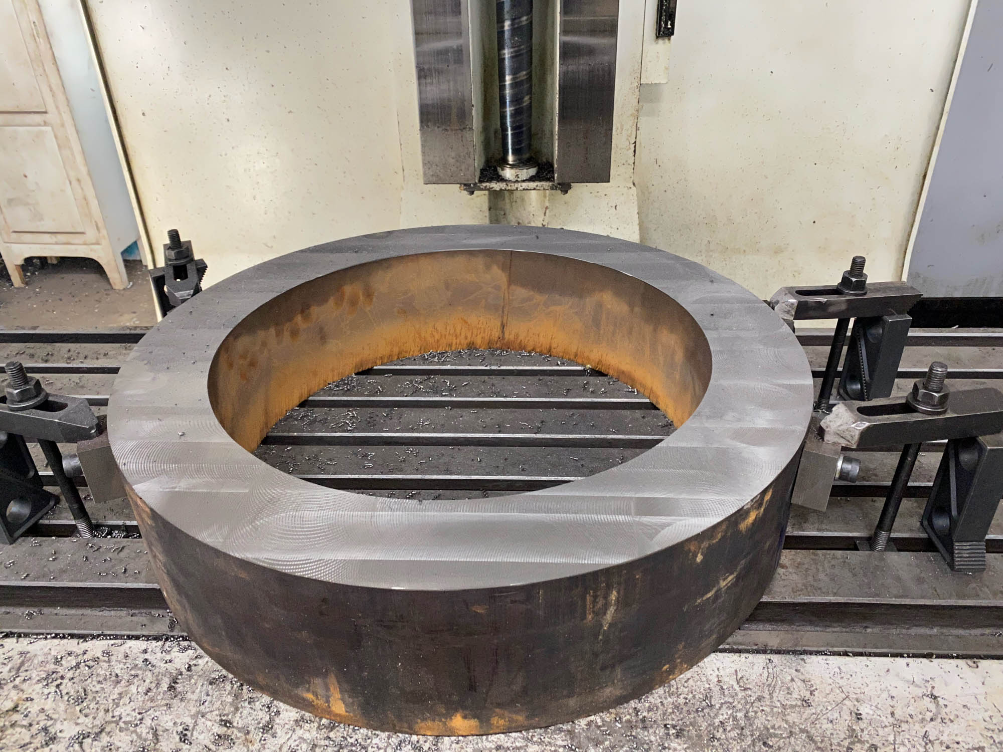
One of the cast iron “blanks” for the new piston bull rings, shown after being water jet cut to rough dimensions. Further machining is required. Steve Pahl photo.
-
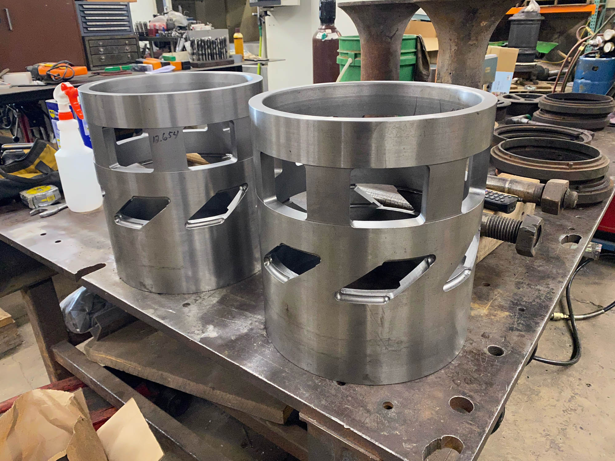
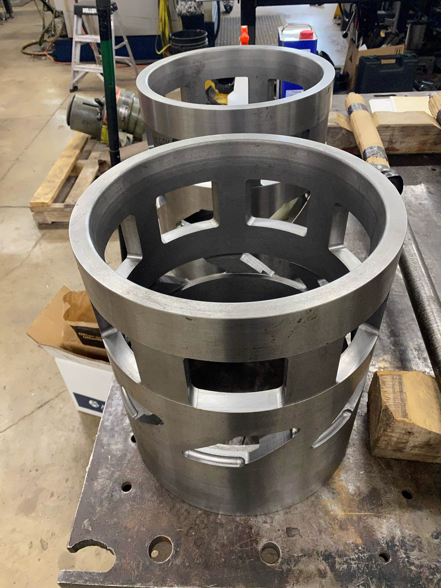
- A valve cage is a hollow cylindrical wear element that is used as both a guide for the valve as well as the outer sealing surface for the valve so it can route both the live steam and exhaust steam to the proper places. The valve packing rings form the inner sealing surface and slide back-and-forth in the valve cage as the valve is moved.
C&NW 1385’s new valve cages stand ready to be installed into the steam chests. Steve Pahl photo.
There are two sets of ports that have been machined into each cage. The large rectangular ports lead to the exhaust nozzle up to the smokebox so the exhaust can be pointed up and out of the smokestack. The smaller parallelogram-shaped ports lead to the passage to the cylinder. Depending on the position of the piston valve inside the cage either the live superheated steam is routed into the cylinder to push the piston forward or back or the cylinder is connected to the exhaust passage to release the steam once it has done the work of pushing the piston. Since steam pushes the piston in both directions there are ports needed for each end of the piston travel and the need for a cage at each end of the steam chest.
-

- Another view of the new valve cage. Steve Pahl photo.
-

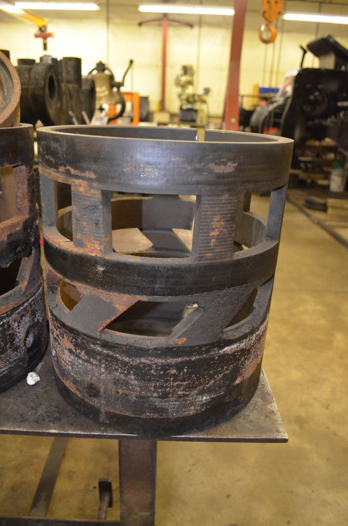
- Comparison view of the old damaged valve cage that is being replaced. Jeffrey Lentz photo.
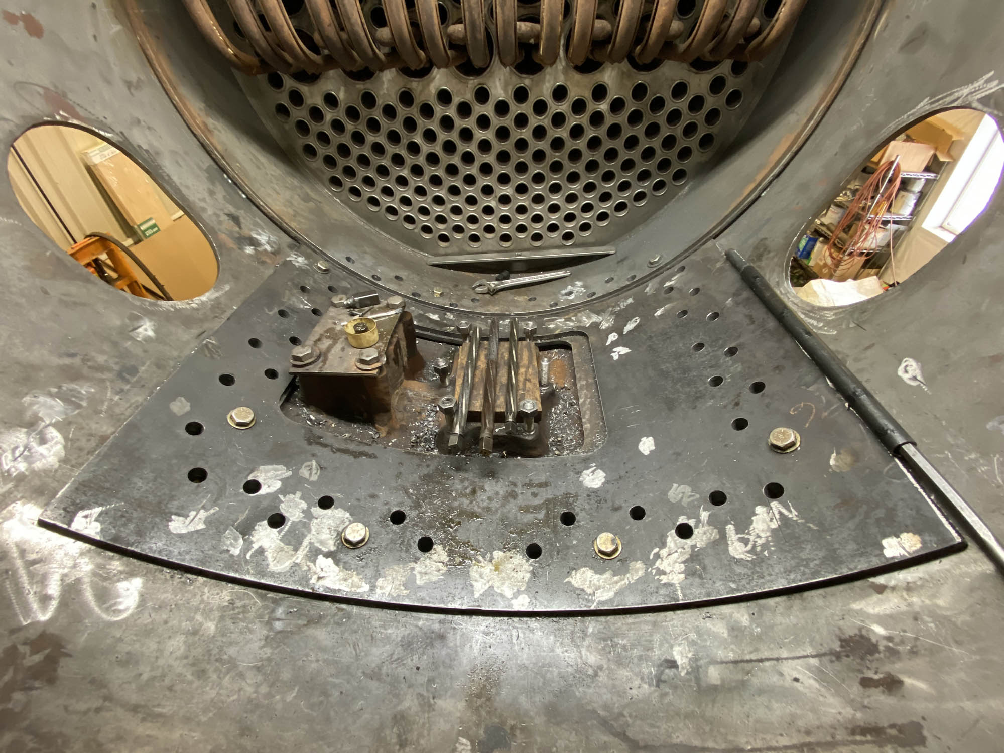
The valve cage on the locomotive’s engineer side has been previously cleaned up by boring and was found to be thick enough to still have a long service life ahead and was therefore left in place. The fireman’s side valve cage was found to be in need of replacement. The new fireman’s side valve cages are now ready to be installed into the steam chest. This will be an interesting process to install. The valve cages will be shrunk using dry ice. In the meantime, a couple of rosebud oxy/acetylene torches will be used to expand the steam chest and if everything goes correctly, the valve cage should slide right in. One cage will be inserted from the front side of the steam chest while the other will be inserted from the rear.
-
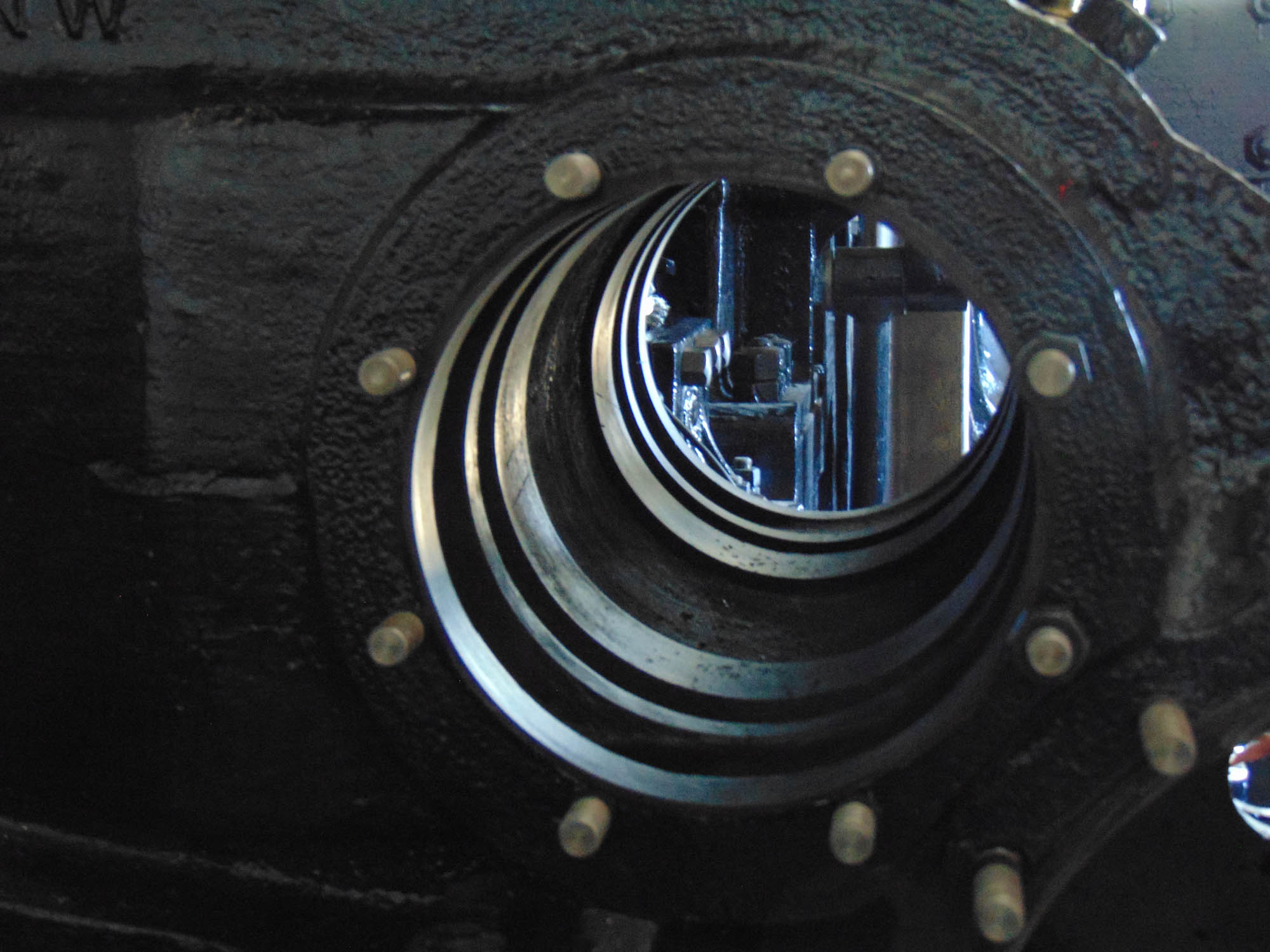
- Looking into the fireman’s side steam chest where the new valve cages will be inserted. M.L. Deets photo
-
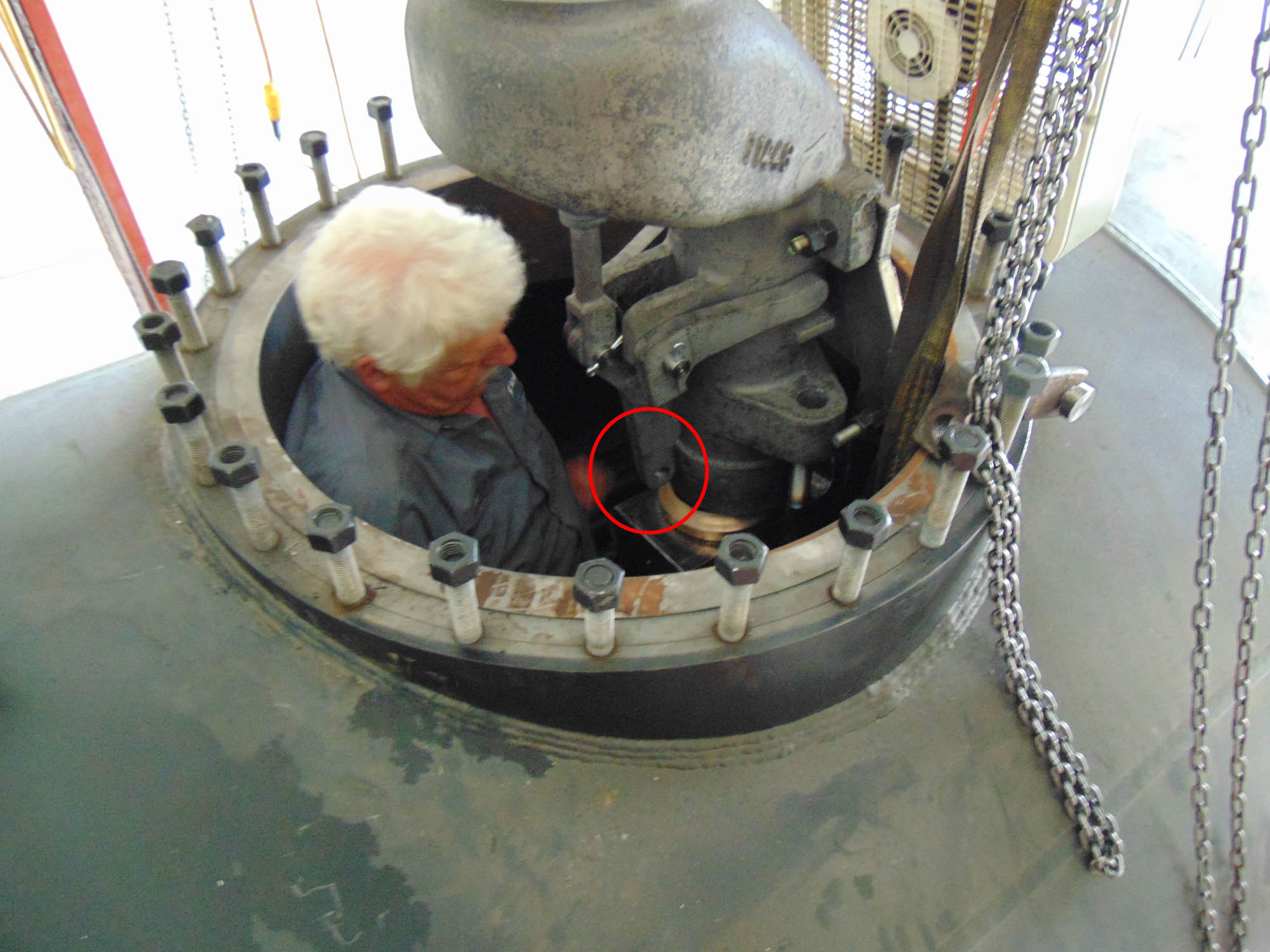
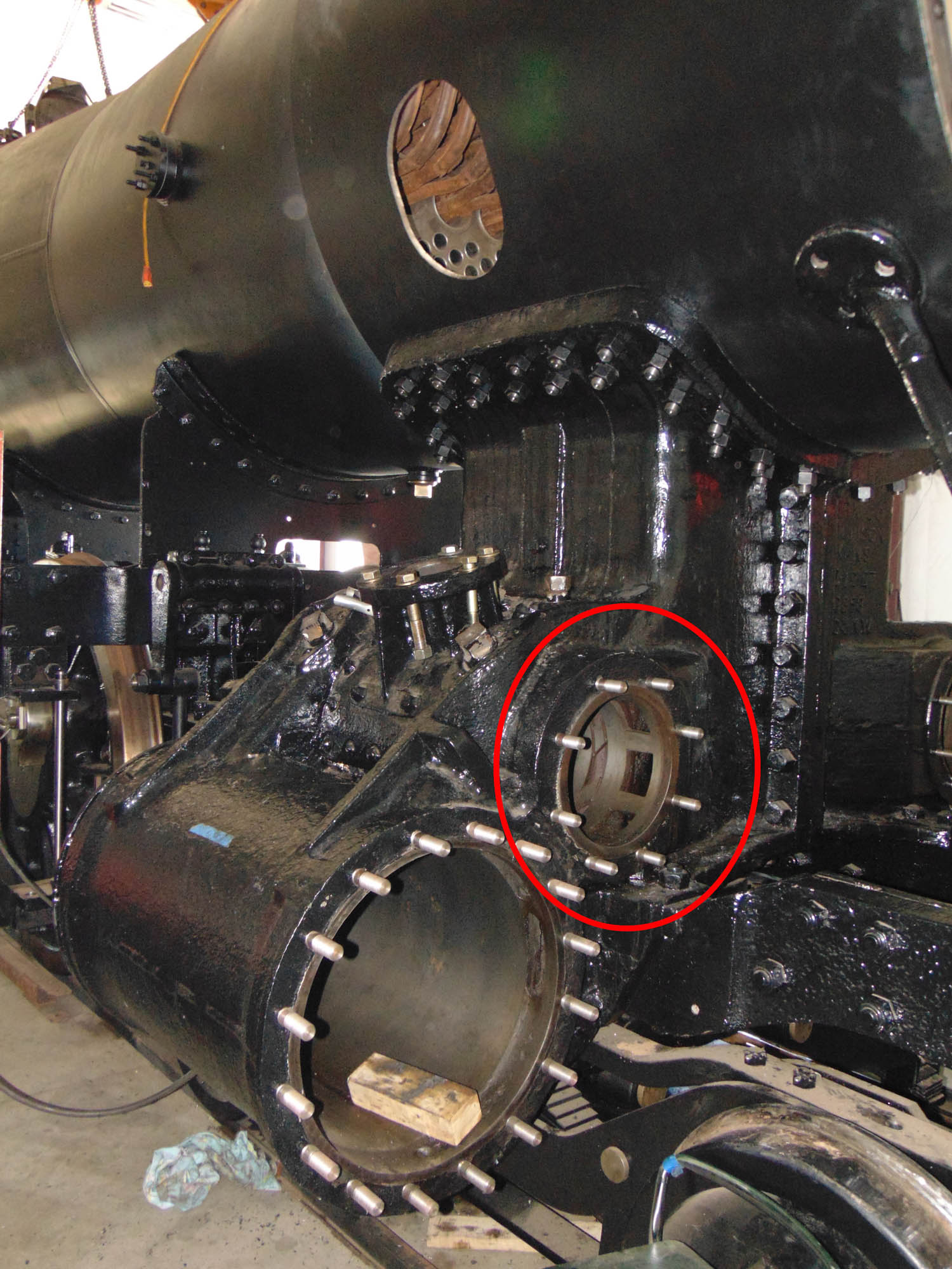
- This broader view shows the engineer’s side of C&NW 1385. Unlike the fireman side, the valve cage (circled) on the engineer side was left in place after boring. M.L. Deets photo.
-
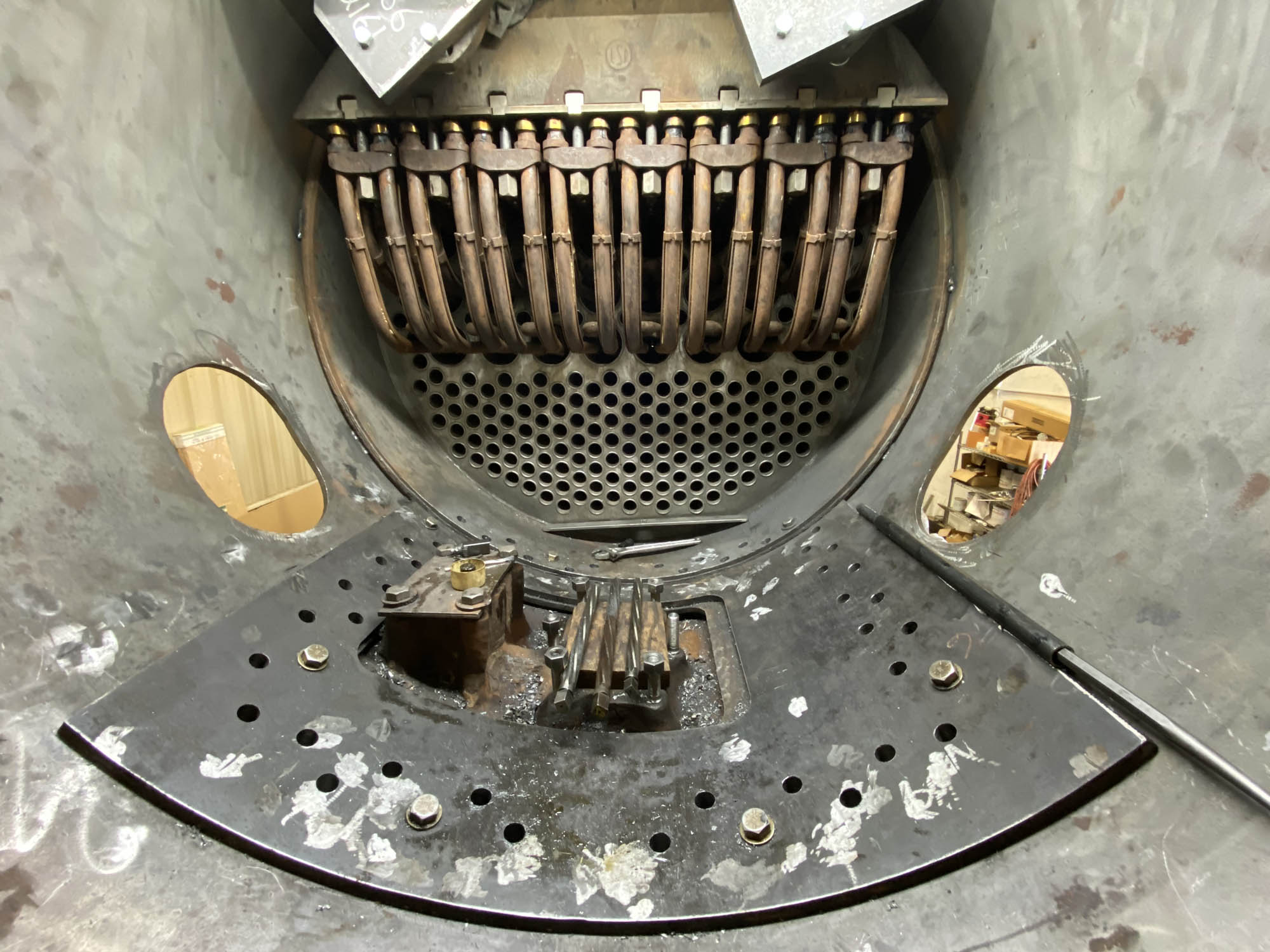
- Fire doors have been painted and await installation. A “spacing” ring needs to be fabricated that will fit between the boiler and the firedoor itself. This is necessary for operational clearance. Due to the change from threaded and peened staybolts to the now welded staybolts, which was by design of the new boiler.
- As mentioned in the December update, the air compressors are awaiting installation. With the new boiler design, there needs to be adjustments made to the mounting brackets and boiler studs to ensure the proper placement as it appeared when MCRM purchased the locomotive. This will also be necessary for the power reverse due to the same circumstance.
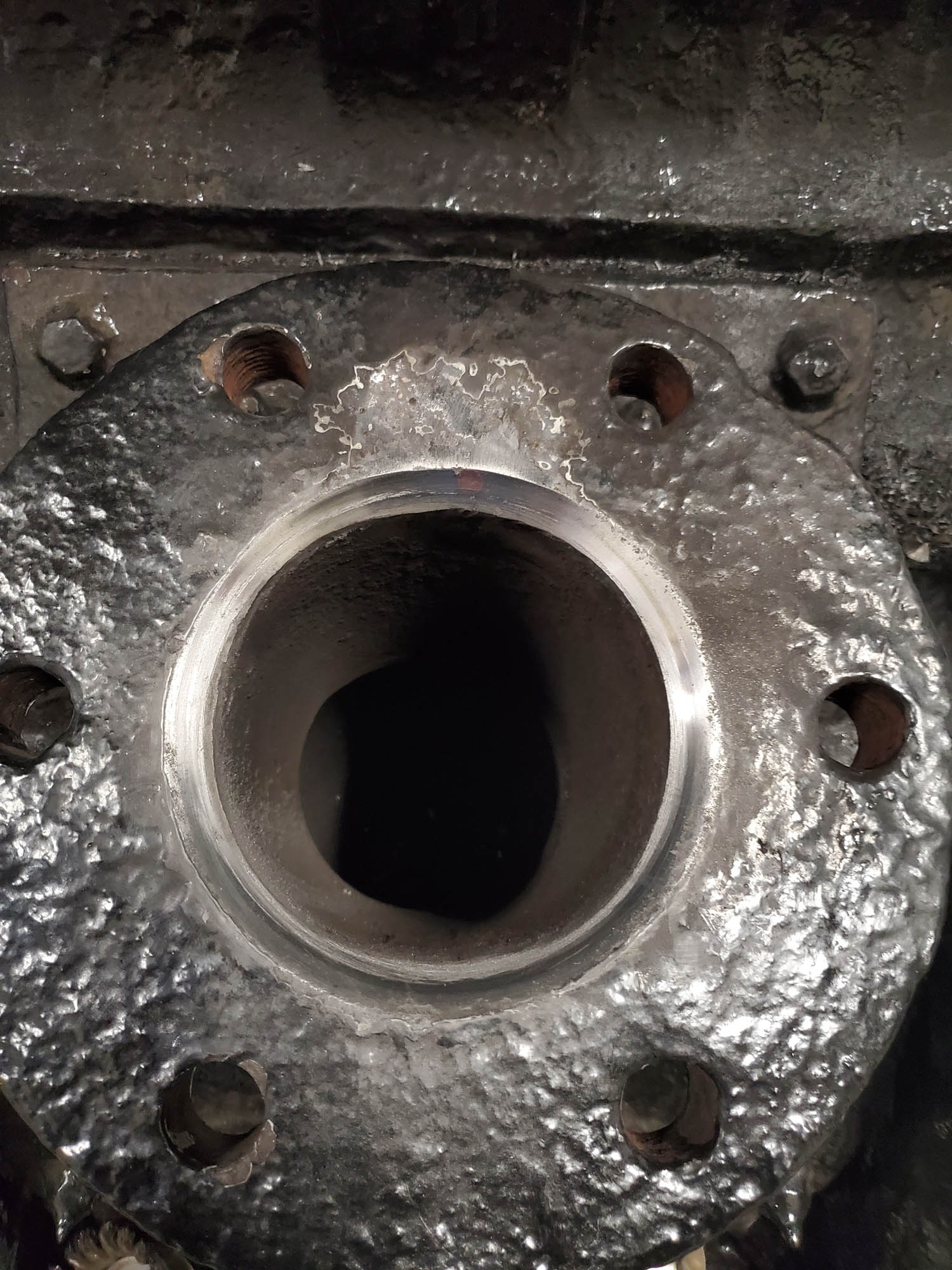
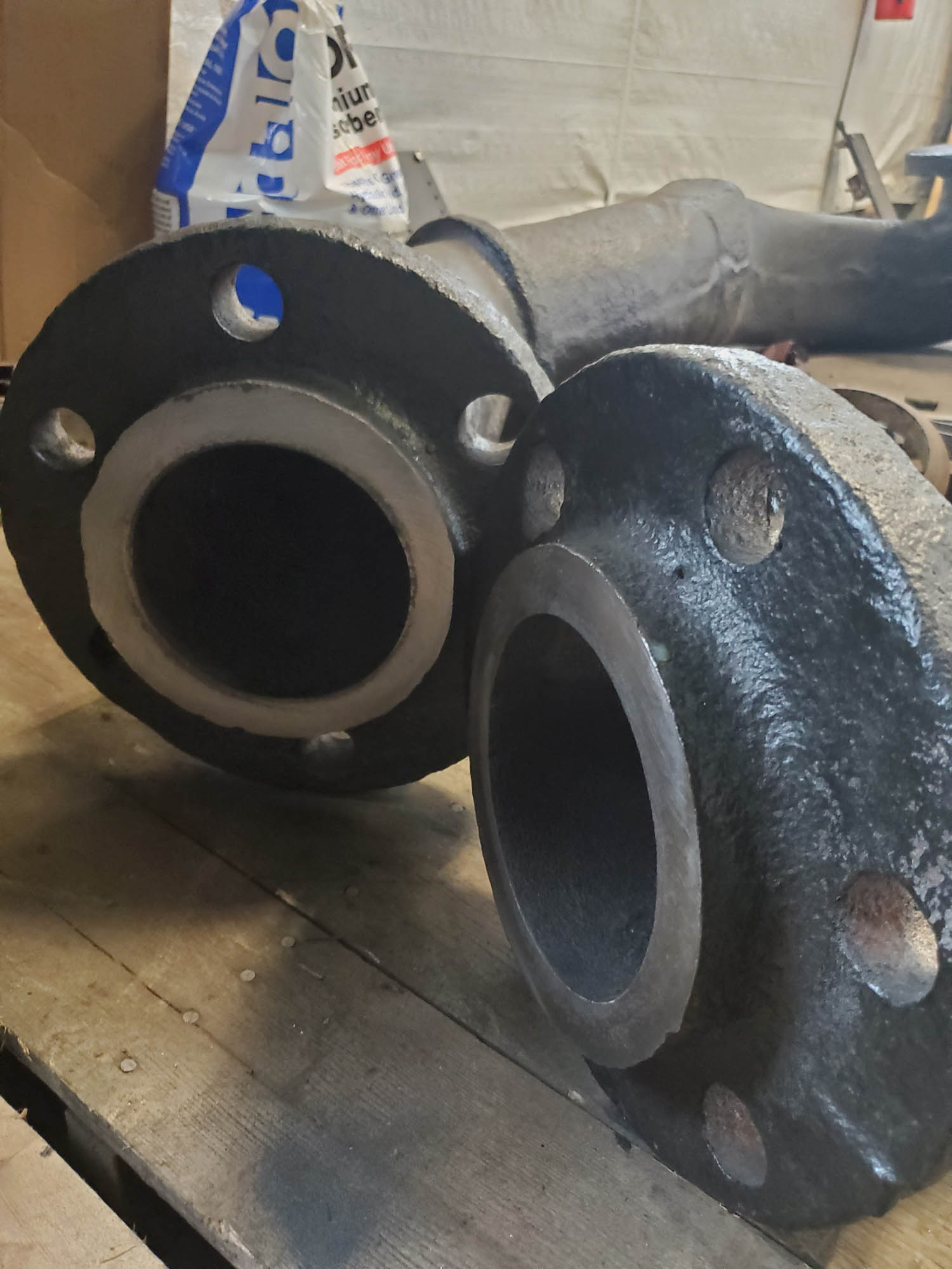
- SPEC Machines made a tool for resurfacing and lapping the seats and flanges on the steam delivery pipes, the superheater header, and the steam chests. This ensures a tight seal for delivering the superheated steam from the superheater header to the steam chests. Work on these existing sealing surfaces is now complete. Yet-to-be-made matching “donuts” will be inserted between the branch pipe and steam chest flanges and the branch pipe and superheater header to adjust for minor manufacturing size differences and space variations between the new and old components.
-
- Flange atop one of 1385’s steam chests showing the new seat surface that has been cut. Tyler Roudebush photo.
-
- Flange atop the other of 1385’s steam chests. Tyler Roudebush photo.
-
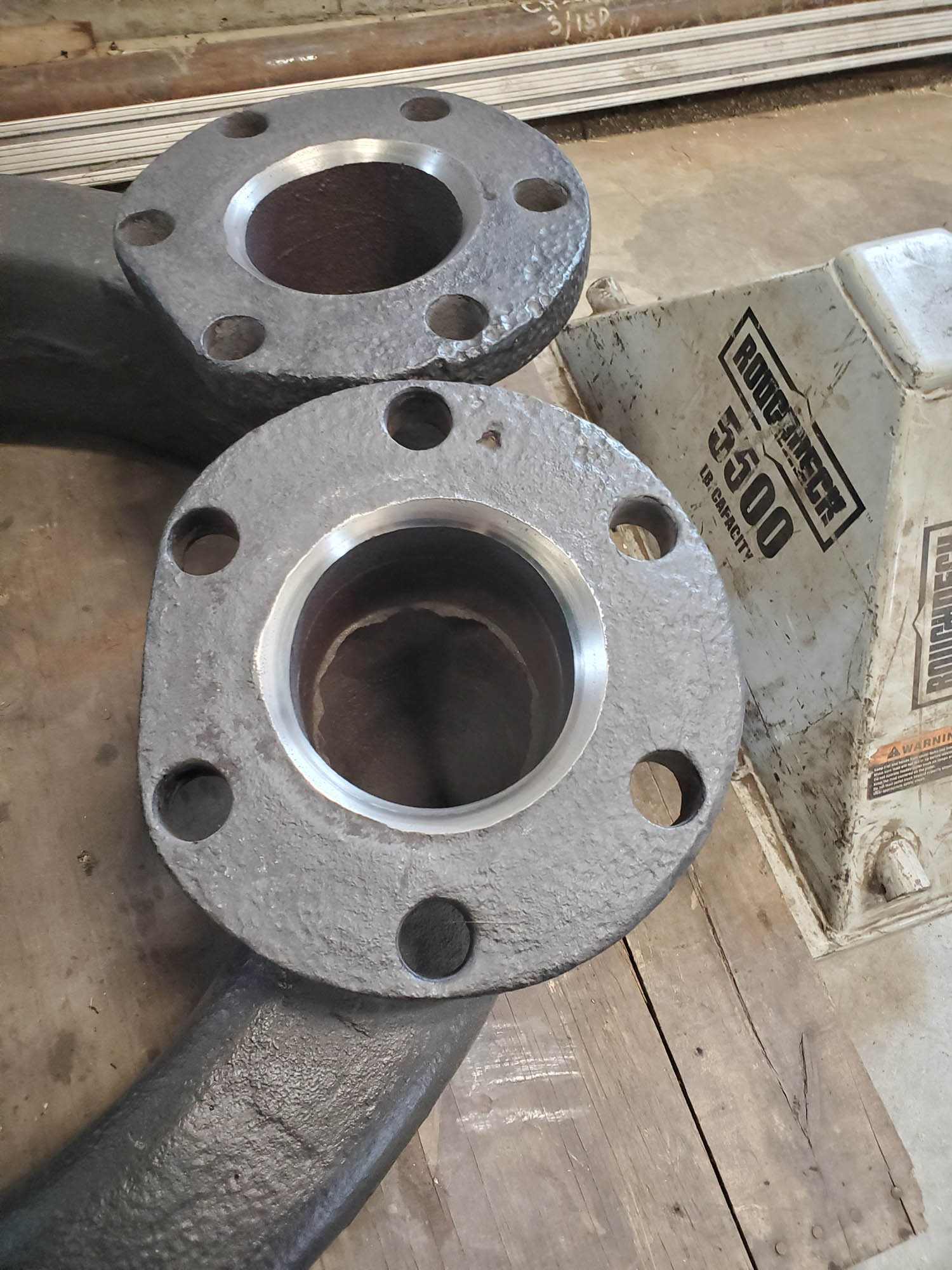
- Newly machined sealing surface at the bottom end of the branch pipes. These carry the steam from the superheater header to the steam chests. Tyler Roudebush photo.
-
- Top end of the 1385 branch pipes with newly machined sealing surface. Tyler Roudebush photo.
-
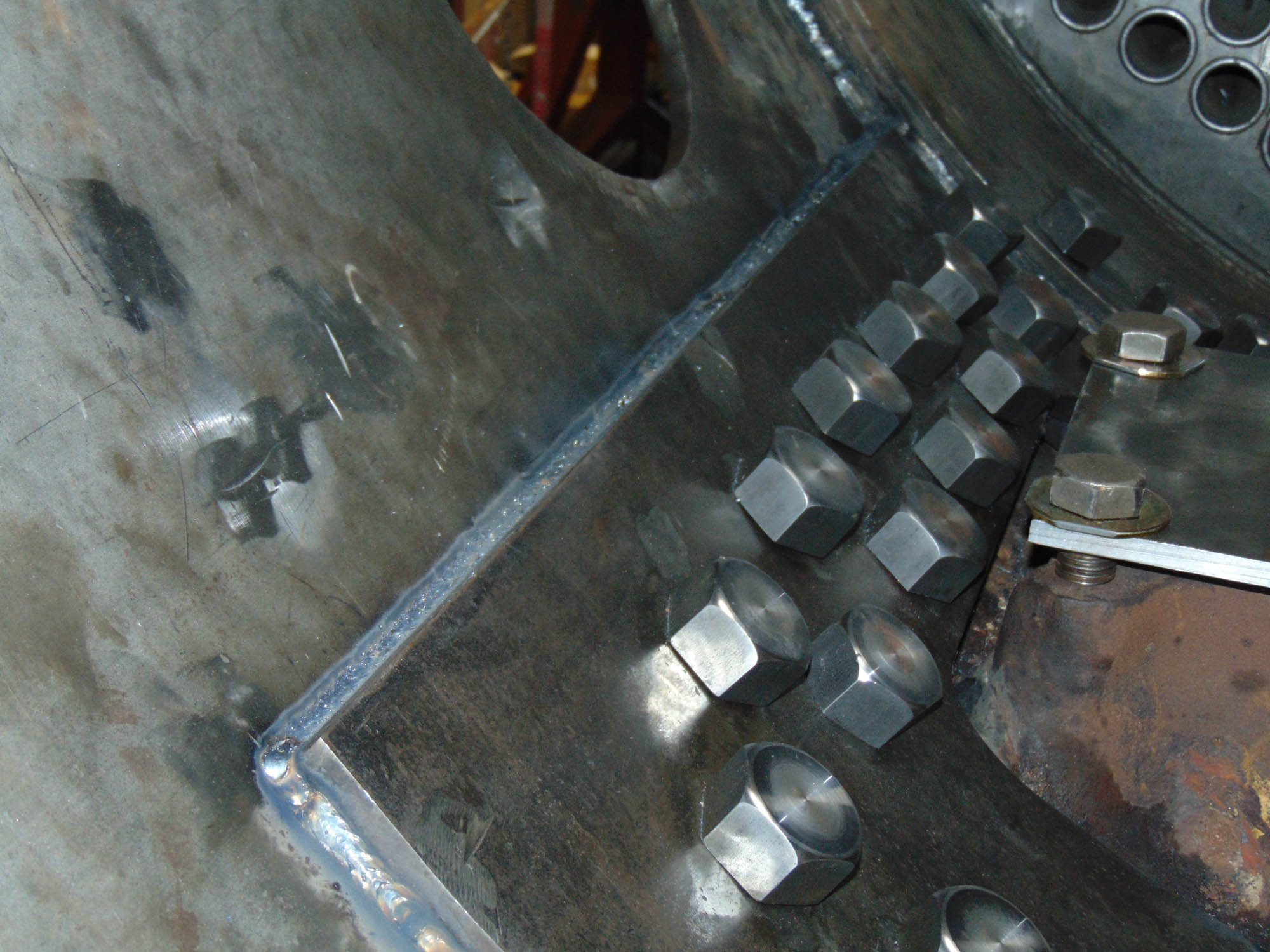
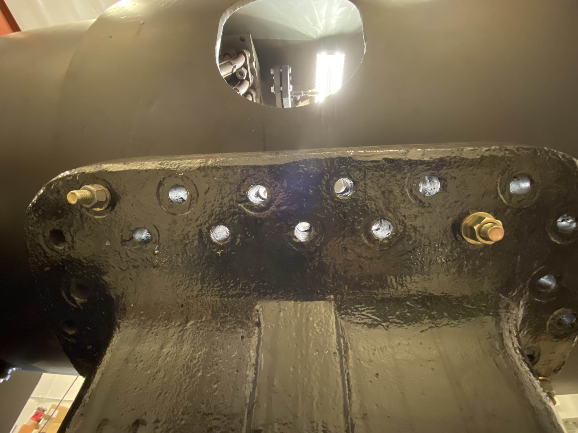
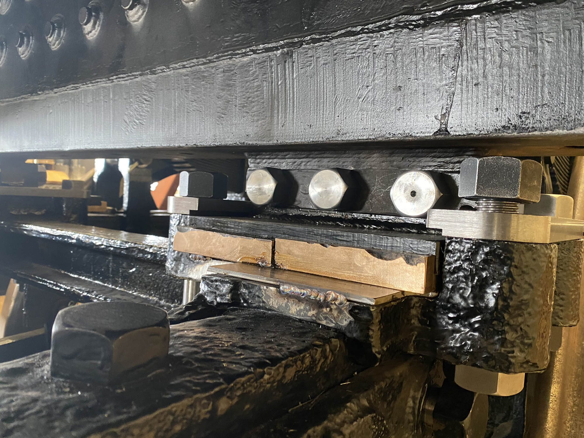
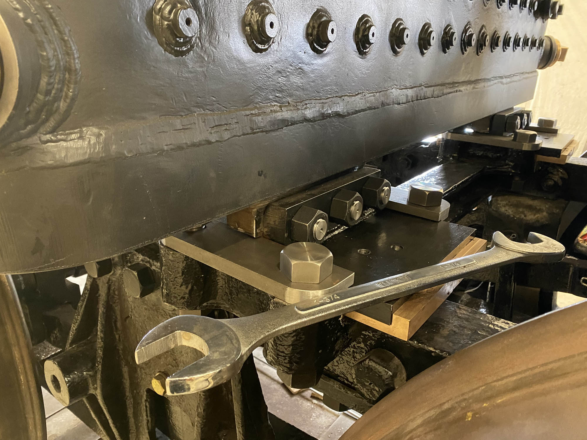
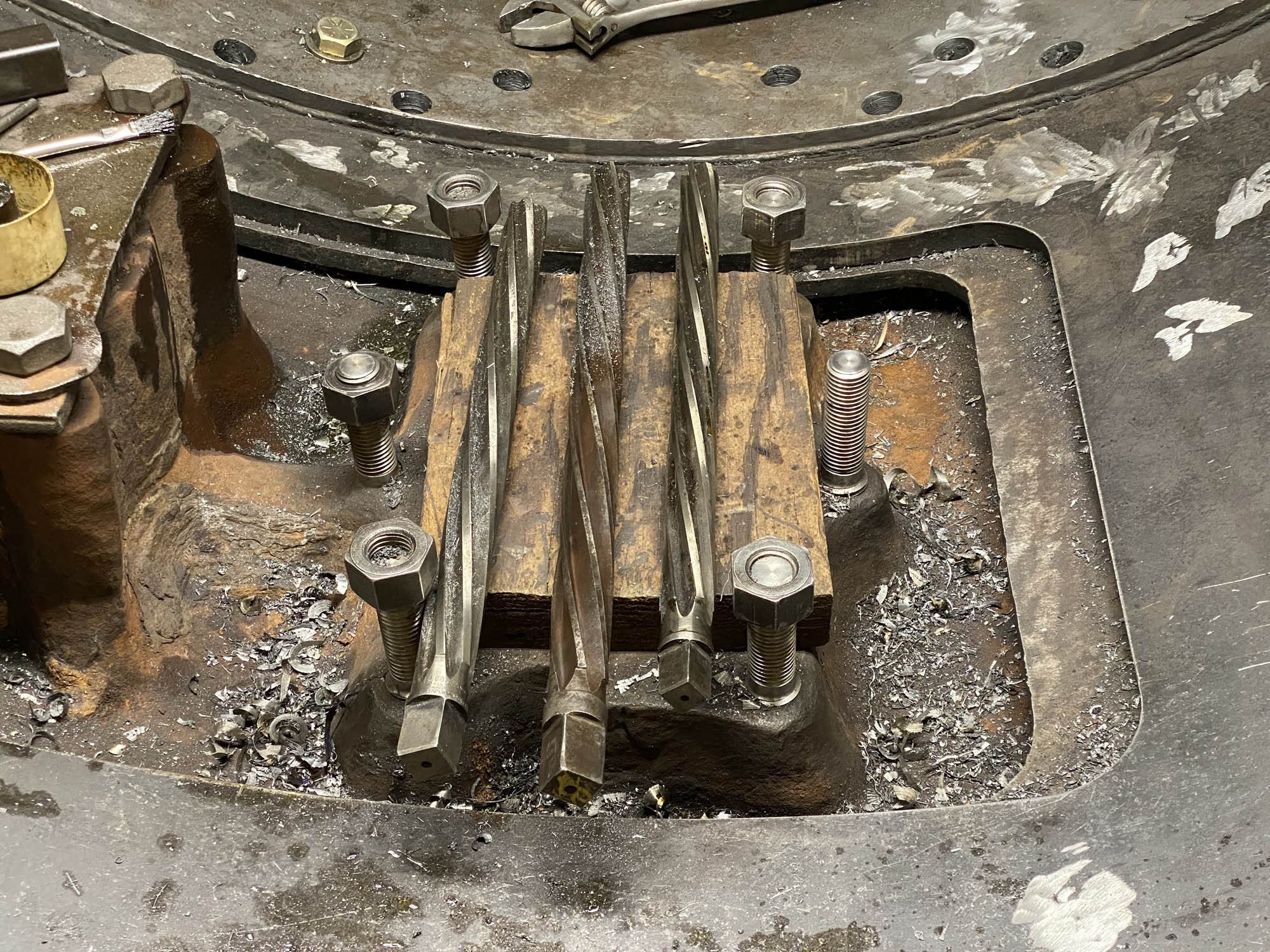
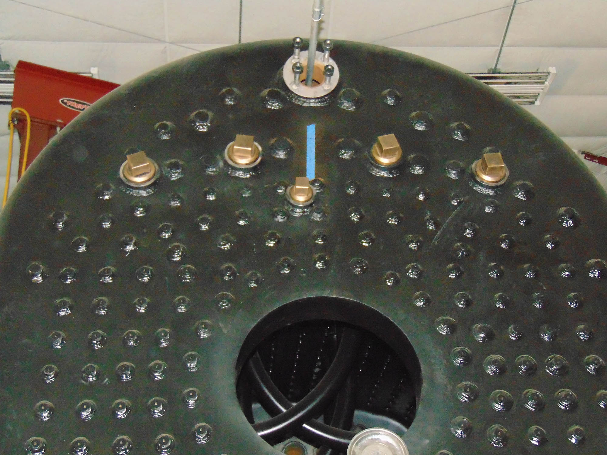
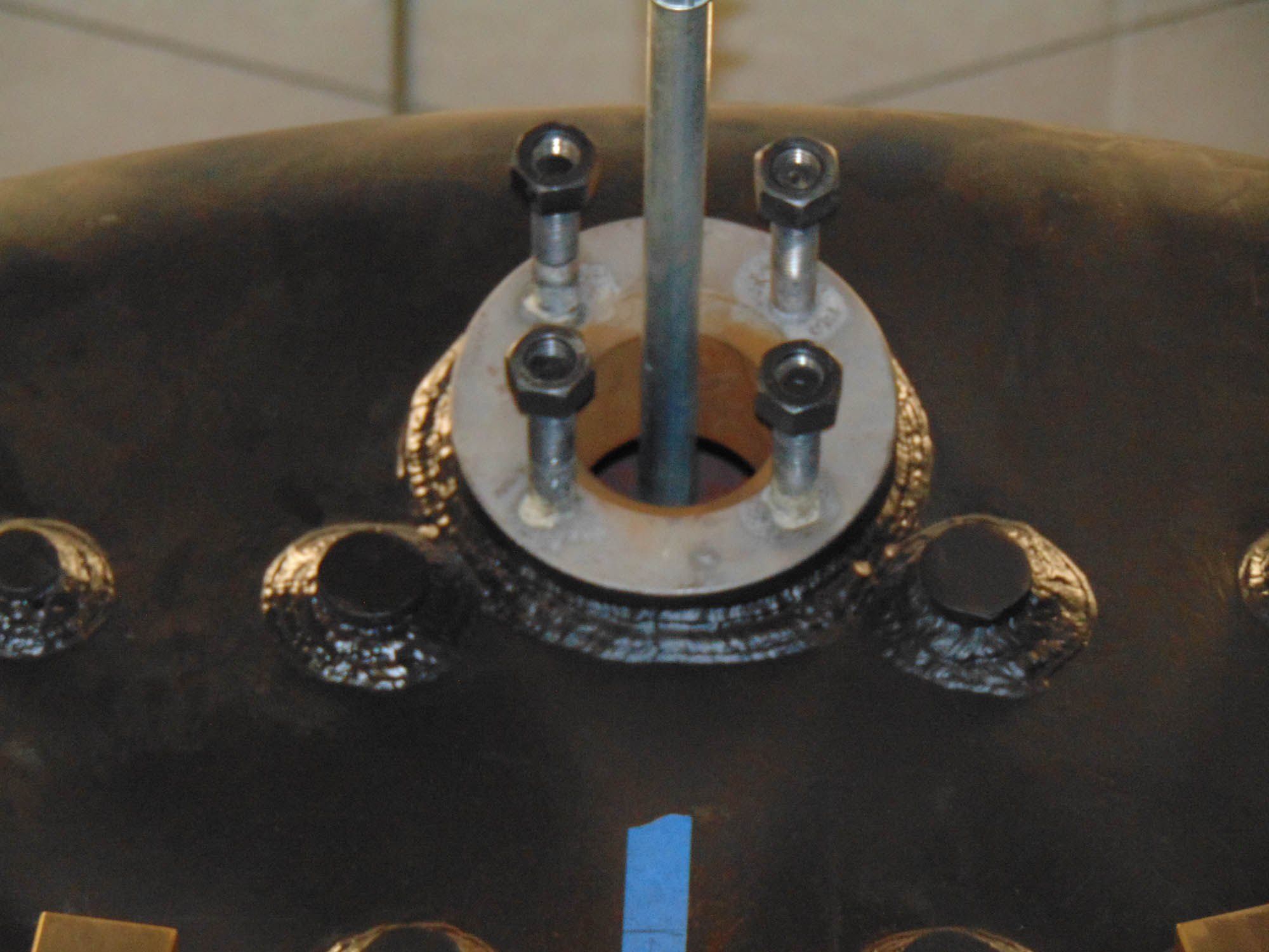
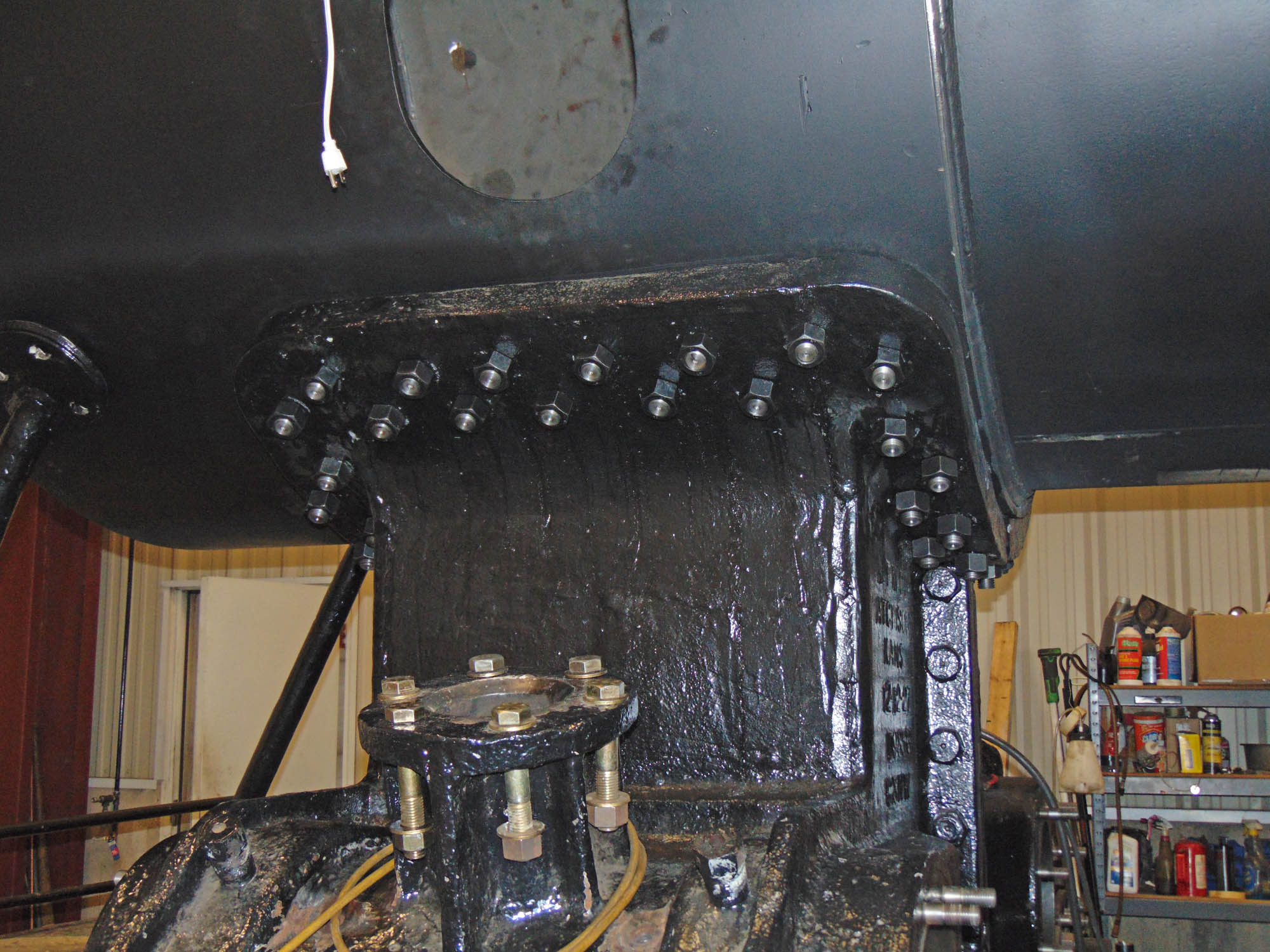
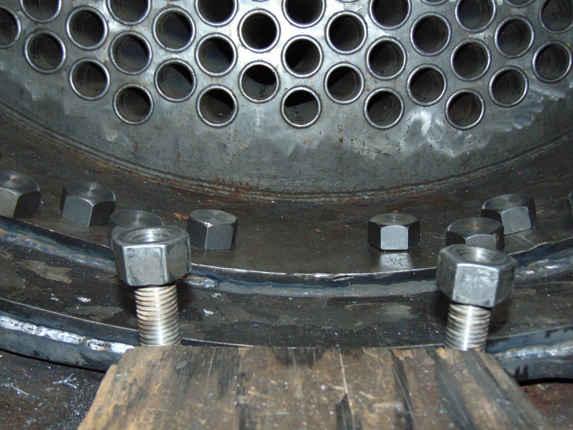
- The smoke box has been seal welded to the boiler. This procedure finally secures the smoke box to the boiler itself. As reported last month, SPEC Machine was busy drilling and reaming the holes that connect the smoke box to the cylinder saddle. I am happy to report that the smoke box is in fact bolted down to the cylinder saddle with 50 tapered fitting bolts custom made by SPEC Machines with 50 H2 heavy nuts. The boiler is now officially attached to the frame! There is still some work to be completed with the smoke box; i.e., complete the grouting at the bottom of the smoke box with refractory, install smoke stack and assorted draft appliances.


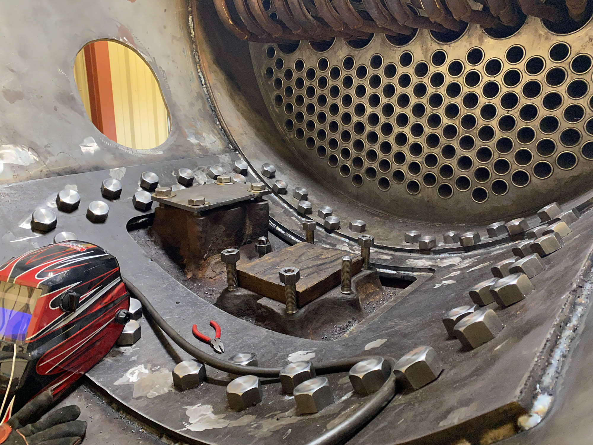
50 custom-made tapered bolts now help secure the smoke box to the cylinder saddle. Steve Pahl photo.
-
- Outside view of bolts securing the smoke box to the cylinder saddle. M.L. Deets photo.
-
- Detail view of the seal weld and bolts along the bottom of C&NW 1385’s smoke box. M.L. Deets photo.
-
- Detail view of the seal weld and bolts along the bottom of C&NW 1385’s smoke box. M.L. Deets photo.