It has been over four months since the last Chicago & North Western #1385 steam status update was posted. What has been happening on the locomotive in that time? The short answer is quite a lot.
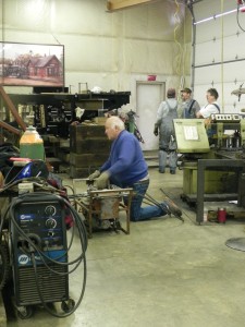
SPEC Machine, located outside of Middleton, Wisconsin, continues to serve as the center of the action under the care of SPEC’s Steve Roudebush and the 1385 Task Force. Work continues on a near daily basis inside the well-equipped shop. Several different tasks are in progress at any given time, allowing for work to continue no matter what hurdles are thrown in the way.
Here are the latest areas of the project undergoing work.
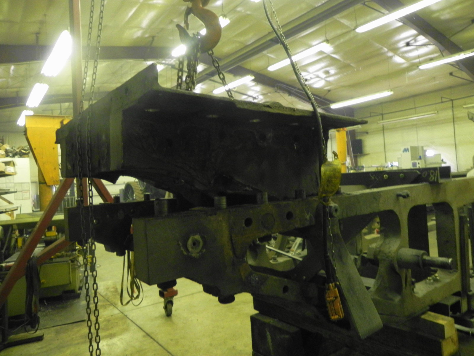
Footplate
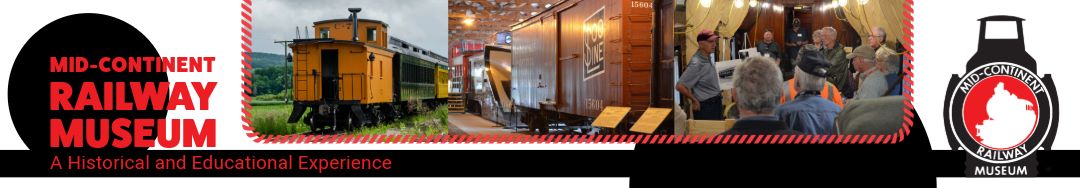
Replacement of the footplate was a time consuming task but is finally complete. The footplate sits between the frame underneath the cab and serves as the connector between locomotive frame and drawbar, thus massive forces are transferred through the footplate when pulling a train. The original footplate casting, already repaired in the past, was found to have more cracks and was deemed unsafe to attempt further repairs. A new weldment was manufactured. It is now fully mounted to the frame using tapered bolts to ensure no movement.
CNW 1385 installed footplate.
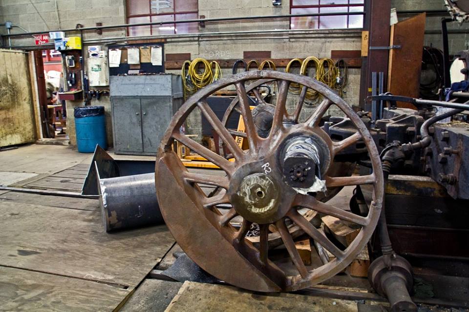
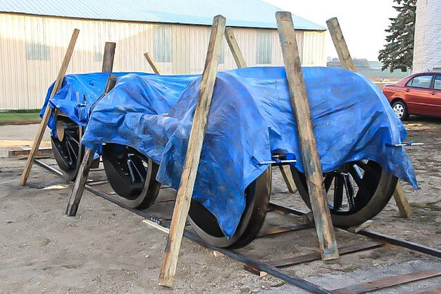
Lead Truck
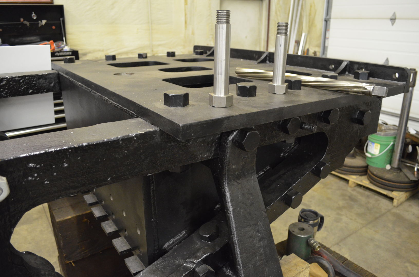
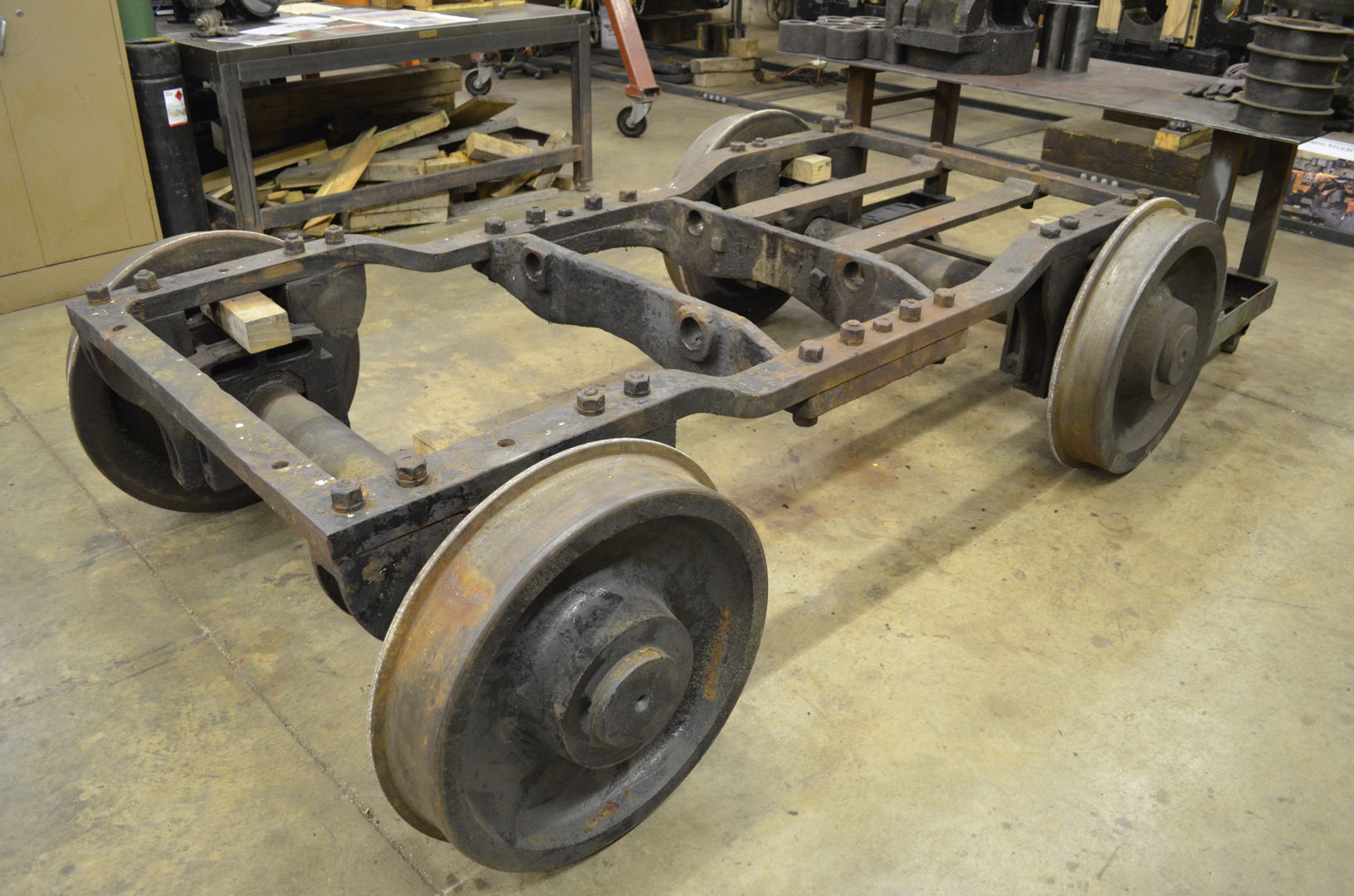
The lead truck is almost fully disassembled. Pins and bushing of the swing link suspension were found to be badly worn and require replacement. The holes in the truck casting where the swing link suspension connected were also worn well out of round and will require welding up and reboring. Inspections also found the bolts holding the jaws to the truck loose, allowing axle wear if left uncorrected.
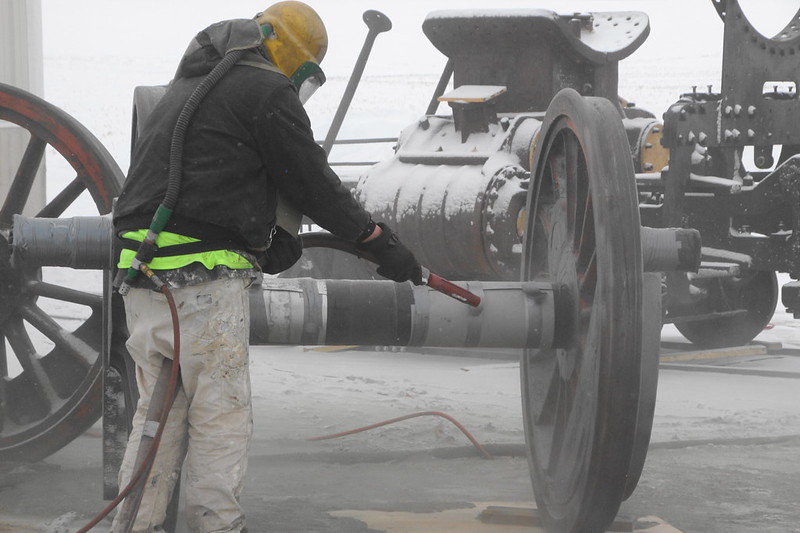
The wheels are being assessed whether they can be turned on a lathe and machined to a proper profile. All wheels were well worn, but only one wheel exhibited significant wear to the flange, but possibly not too much as to not be fixed with a session on a lathe. If turning the wheels are possible, it would save what could be a rather involved process of trying to locate a suitable replacement wheel or wheels.
-

- CNW 1385 lead truck.
-

- CNW 1385 lead truck components.
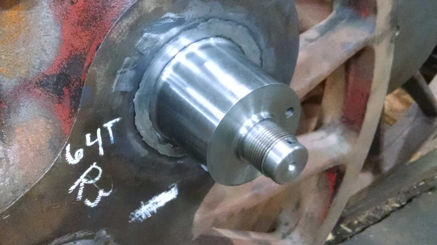
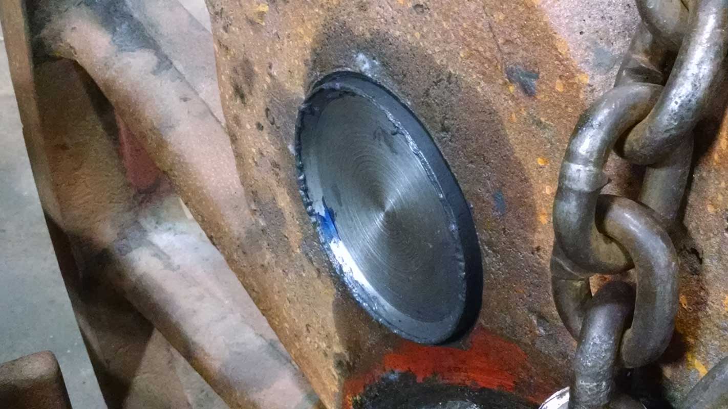
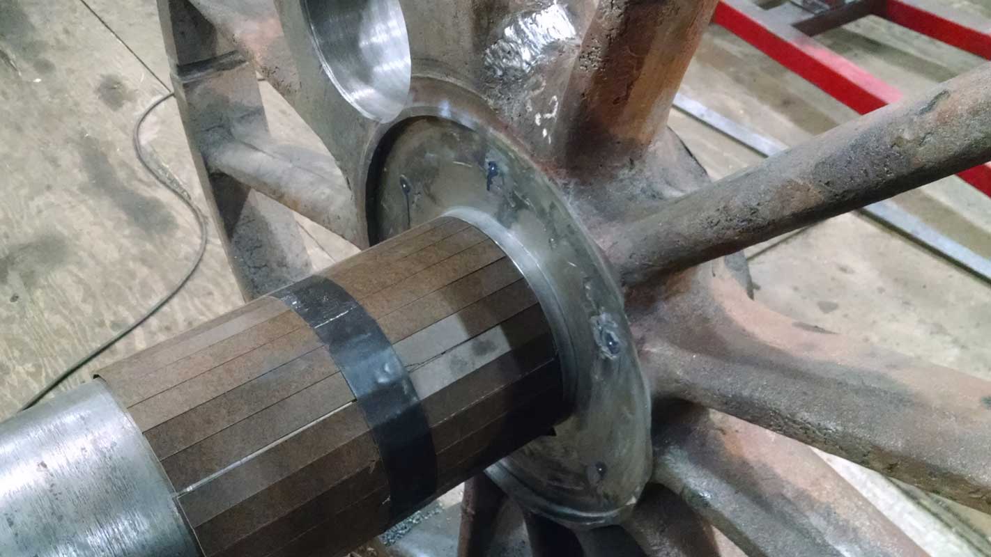
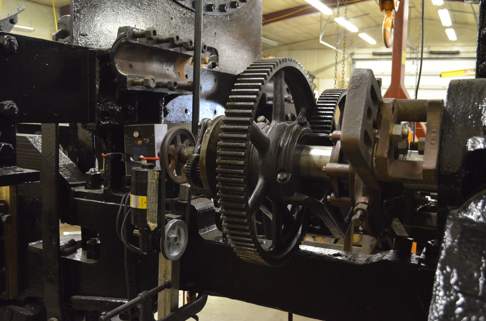
Crown Brasses
Four out of the six driving wheels’ crown brasses were found reusable after machining. The remaining two had to be replaced with new brasses due to being too thin according to American Locomotive Company and C&NW specifications. The reused brasses are expected to be able to be turned once or twice more before they too require replacement.
-
- Crown brass installed in driving box.

-
- Crown brass installed in driving box.

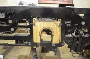
Spring Rigging
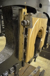
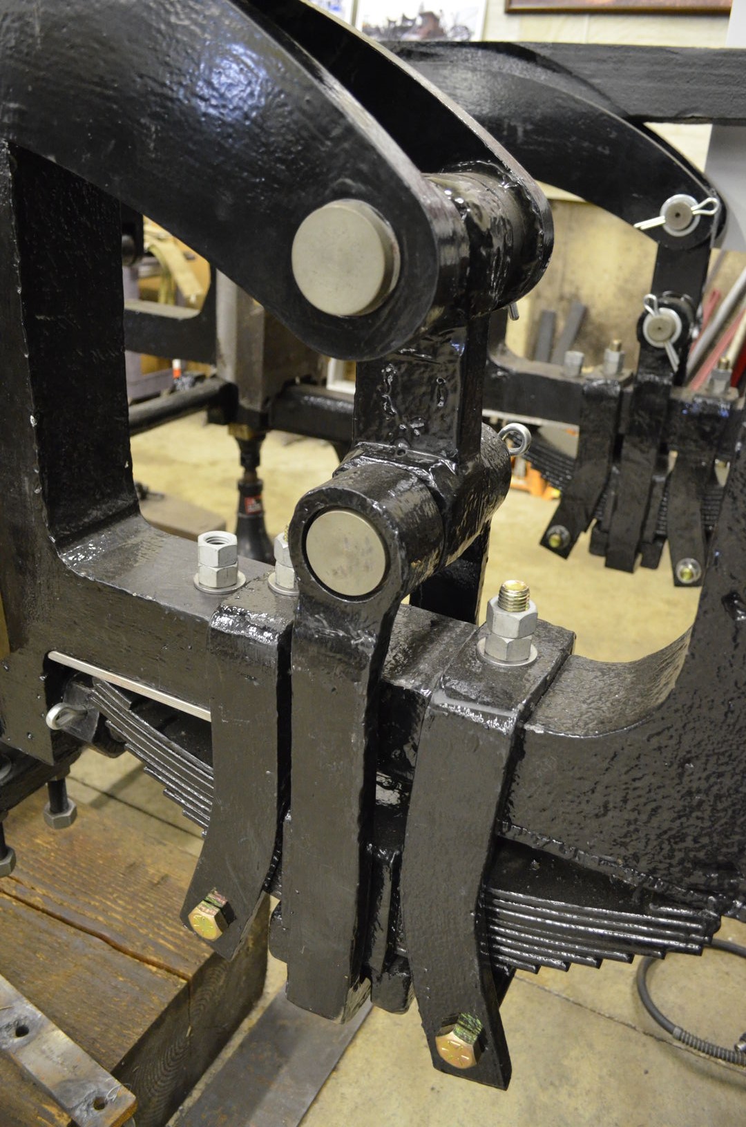
The spring rigging is fully installed. New pins and sleeves were installed throughout. Some had been replaced in the past using improper material which caused excessive wear not only to the pins and bushings, but also caused excessive wear to other spring rigging components. Some of the beams were found to be worn thin enough to cause concerns over the safety of welding up and reboring. Instead those equalizing beams were replaced with new custom fabricated beams.
The springs underwent a deflection test. All springs proved to have near-equal deflection, meaning they are all equally good or equally bad. Equality among spring deflection is desirable so as to avoid one set of springs taking on more weight than the others.
-
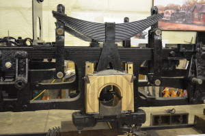
- Spring rigging installed on the CNW 1385 frame.

-

- Detail of new equalizing beam and pins.
-
- Replaced spring rigging equalizing beam worn thin from use.
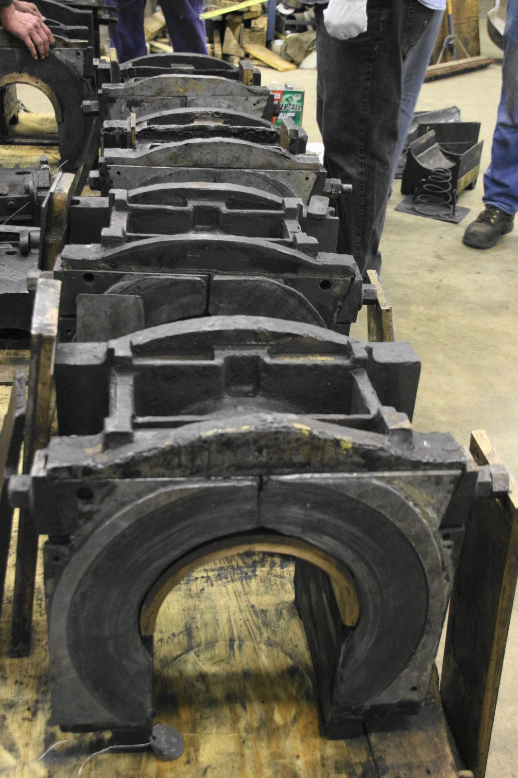
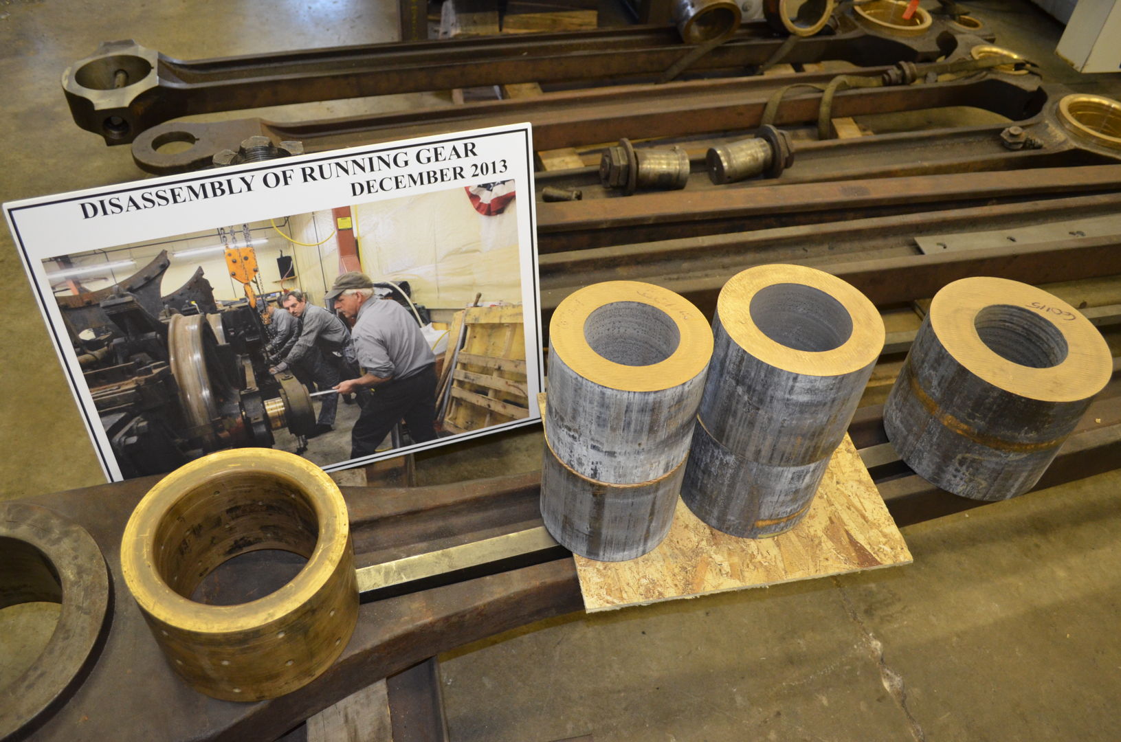
Rod Brasses
The rod brasses fit inside the locomotive rods and accept the wear associated with the movement of the rods (which serve to connect the wheels to the piston and to one another so that driving force can be applied).Four out of twelve brasses were found to be in serviceable condition. They were machined and reinstalled. The remaining eight brasses were replaced with new brasses machined on the lathe.
Delays were encountered in this process due to the materials taking time to arrive and subsequent computer hiccups with the CNC machine. Fortunately, the malfunction did not occur while machining the expensive brasses. Following the computer’s sudden bit of moodiness, substantial testing of the repaired CNC machine followed prior to resuming brass work.
-

- CNW 1385 rod brasses.
-
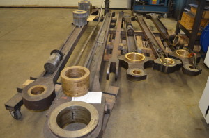
- CNW 1385 rods and rod brasses.

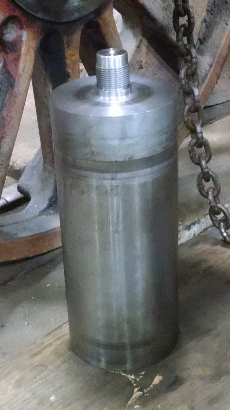
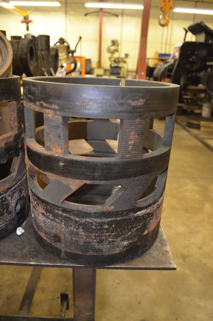
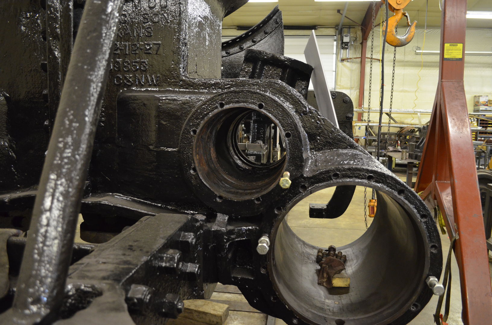
Valve Cages
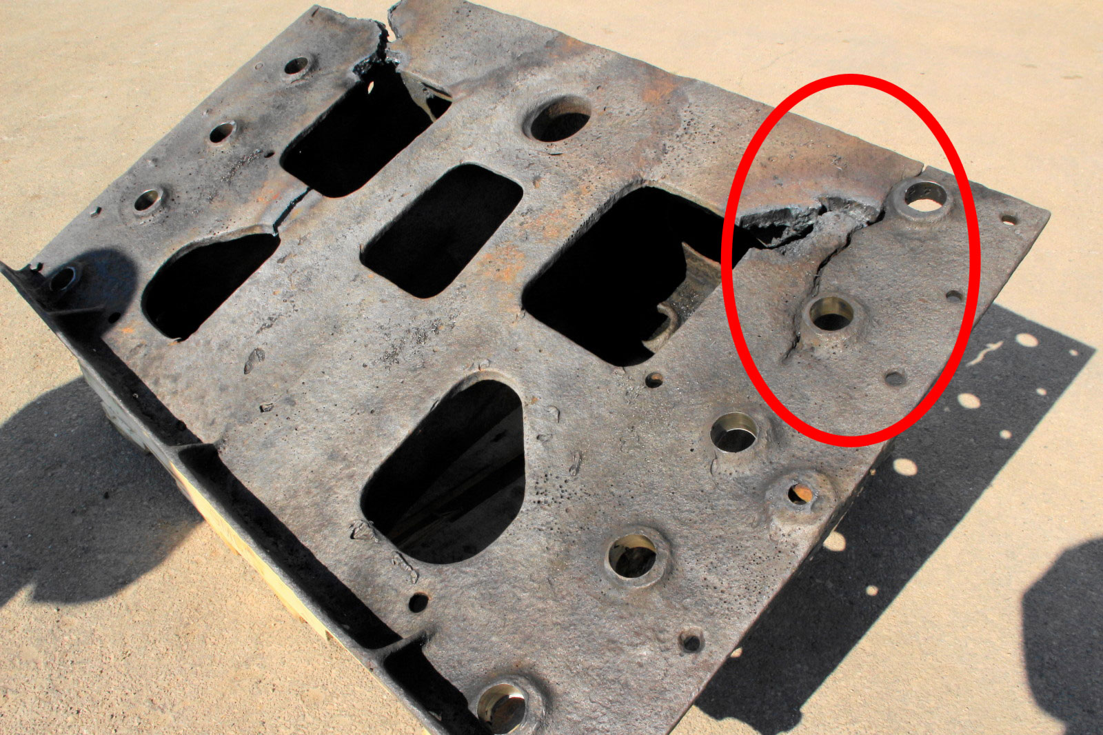
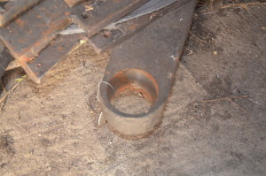
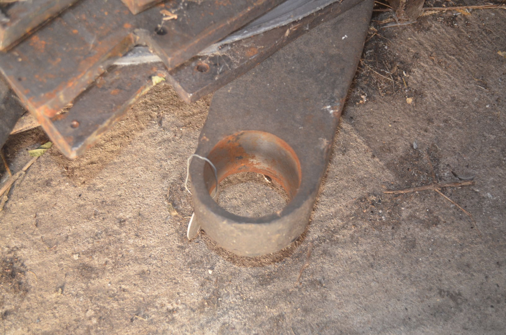
Valve cages fit within the valve bore and house the valves which control the admission of steam into the main cylinders. The fireman’s side valve cage was found to have broken pieces requiring replacement of the cage. Cuts to the cage were made to allow for its removal. The engineer’s side valve cage was found to be serviceable and is undergoing reboring.
The use of the CNC milling machine on the brasses is an example of using recent technological advancements to repair the historic C&NW 1385. However, when it comes to reboring the valve and cylinder bores, the 1385’s team have gone decidedly old school by bringing out Mid-Continent’s Underwood Boring Machine, a tool nearly as old as the locomotive it is repairing.
-

- Comparison view of the old damaged valve cage that is being replaced. Jeffrey Lentz photo.
-

- Fireman side cylinder casting awaiting replacement valve cage installation and re-boring.
-

- Underwood Boring Machine.
-
- Underwood Boring Machine.
C&NW 1385 project volunteer Pete Deets explains the operation of the Underwood Boring Machine in the following video.
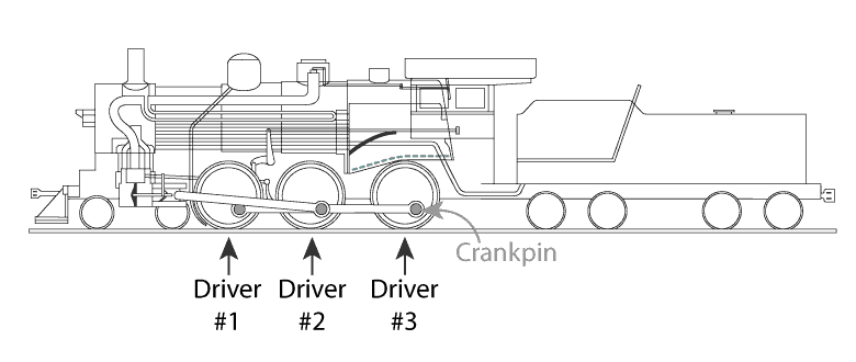
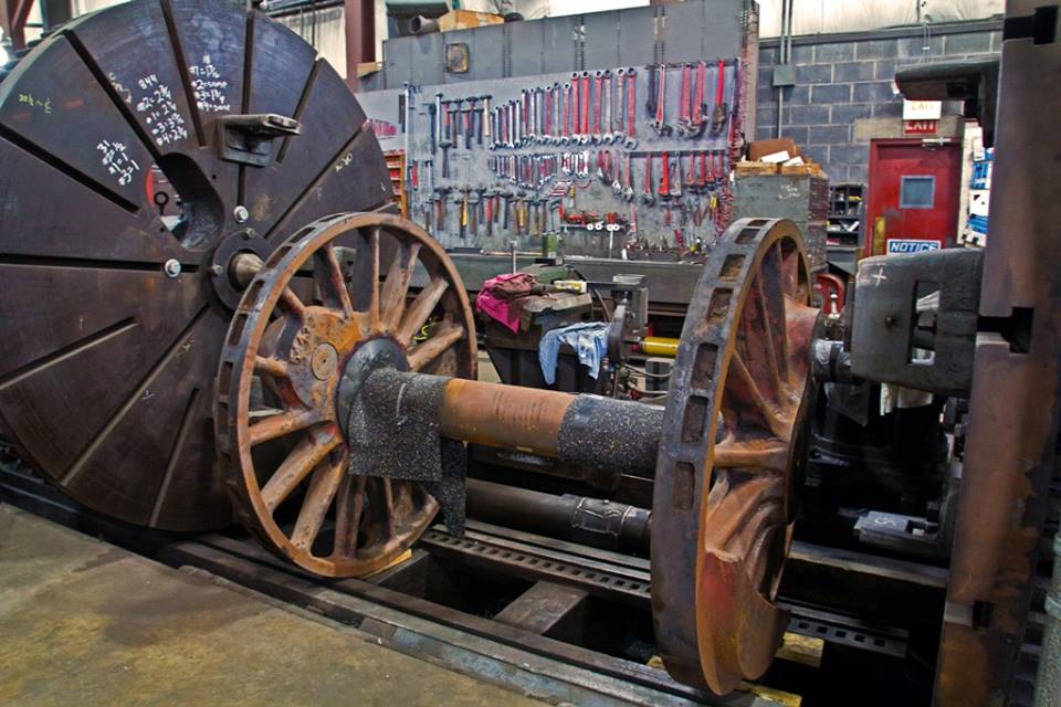
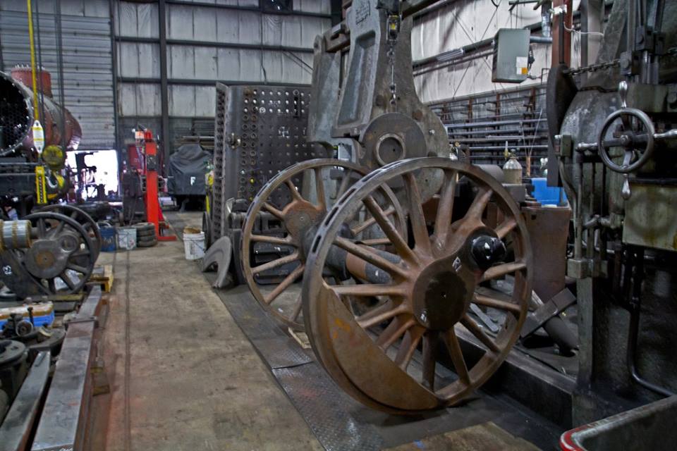
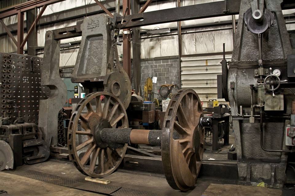
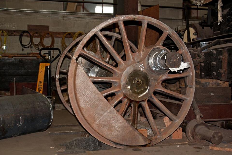
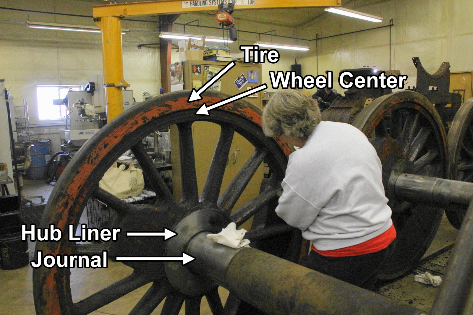
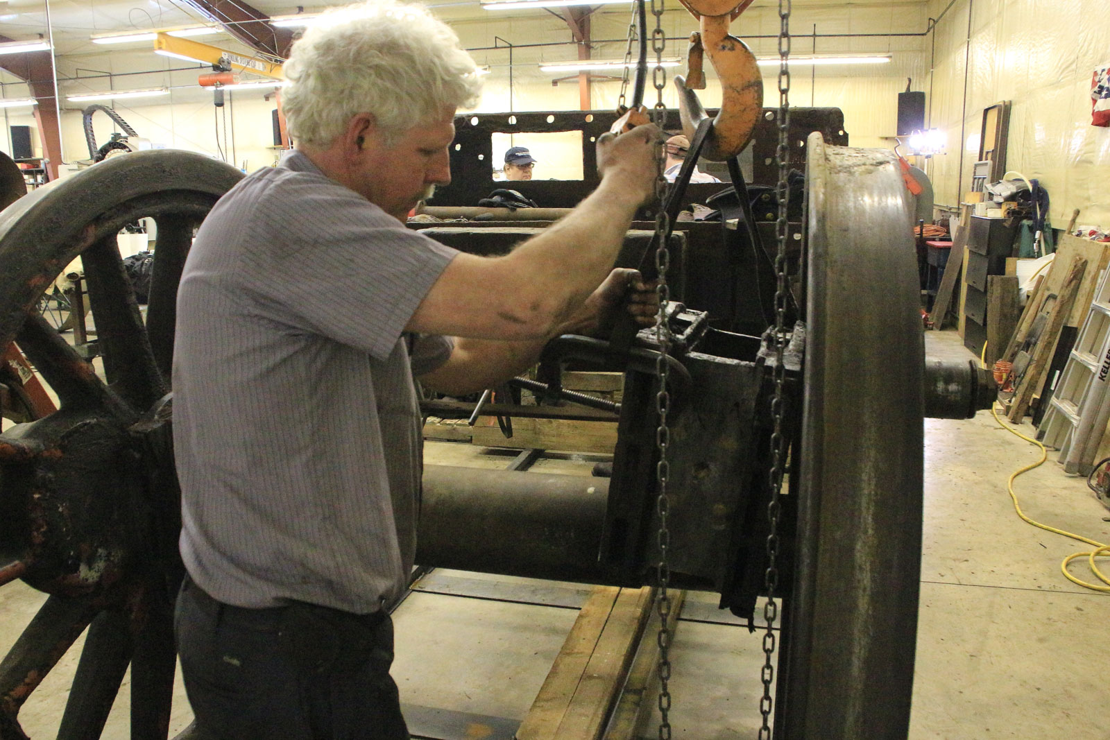
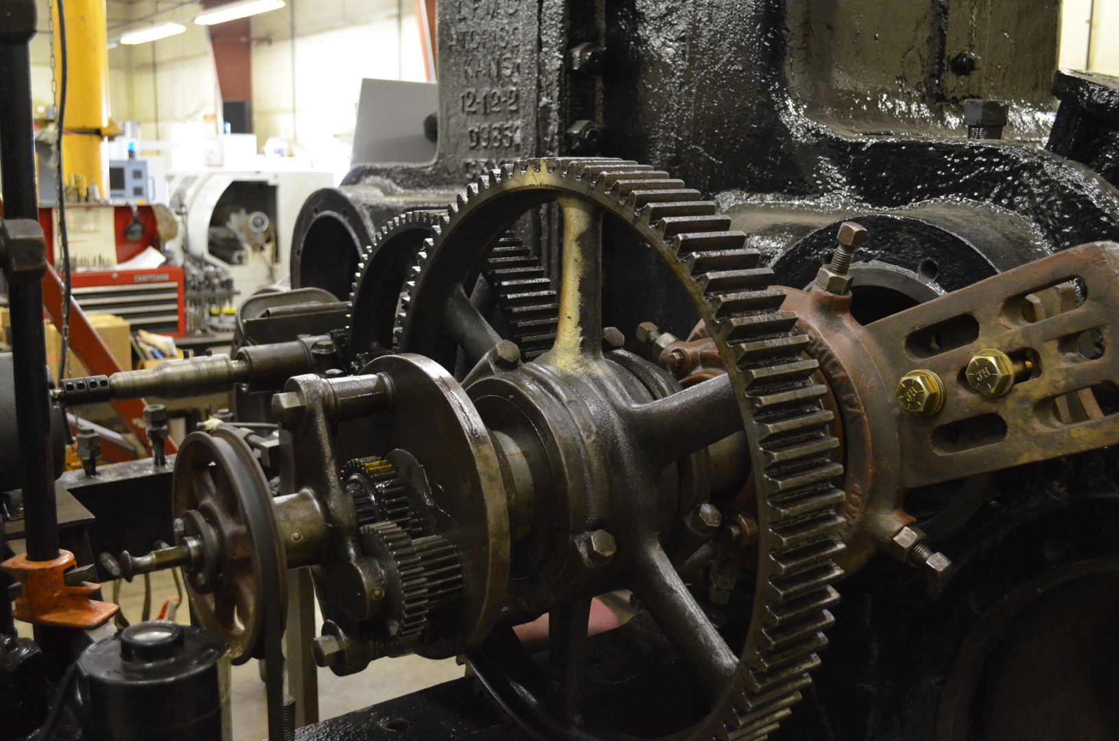
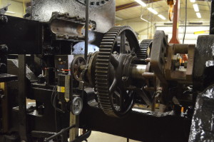
Driving Wheels and Rods
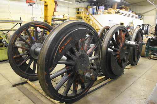
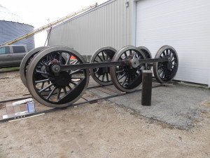
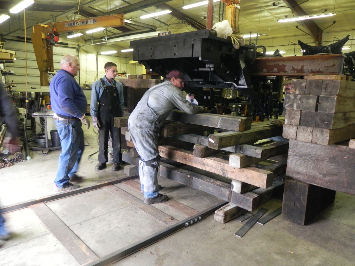
In early November, volunteers descended on SPEC Machine to help with the task of reattaching the newly cleaned and polished rods to the driving wheels and getting them back under the frame. This is no small task as the main driver weighs in at a hefty 15,000 lbs. and each of the two other drivers weigh roughly 10,000 lbs. each. They first needed to be connected together with the also quite heavy side rods, and then all 35,000 pounds of driving wheels plus side rods rolled down the temporary track into position under the frame. Before this could happen, the frame and attached parts, well over 40,000 lbs. itself, had to be jacked up high enough for the wheels to pass underneath. This was accomplished through a hydraulic jack and carefully constructed cribbing. Volunteers involved include Richard Potthast, Mike Wahl, Ed Ripp, Kyle Gherke, Guy Fay and Pete Deets.
-
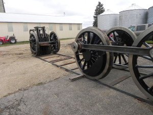
- CNW 1385 drivers being set for connecting the rods. Photo courtesy SPEC Machine.

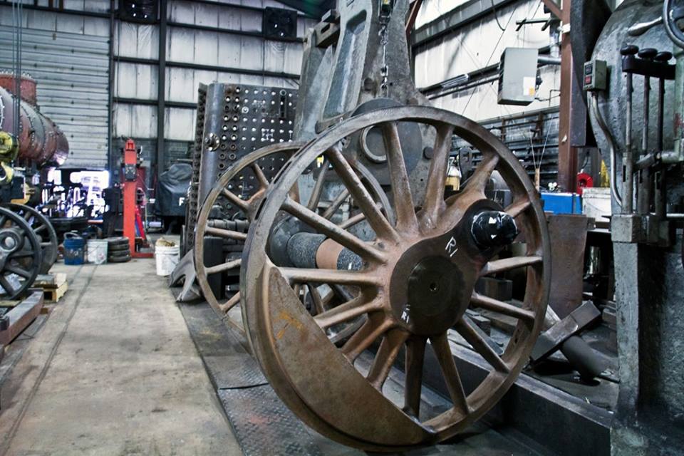
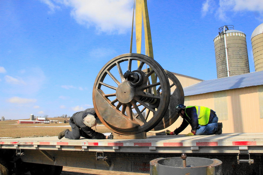
-
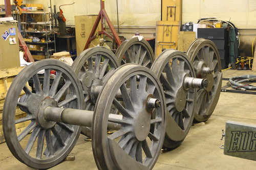
- CNW 1385 drivers connected with rods, ready to be rolled under frame. Photo courtesy SPEC Machine.

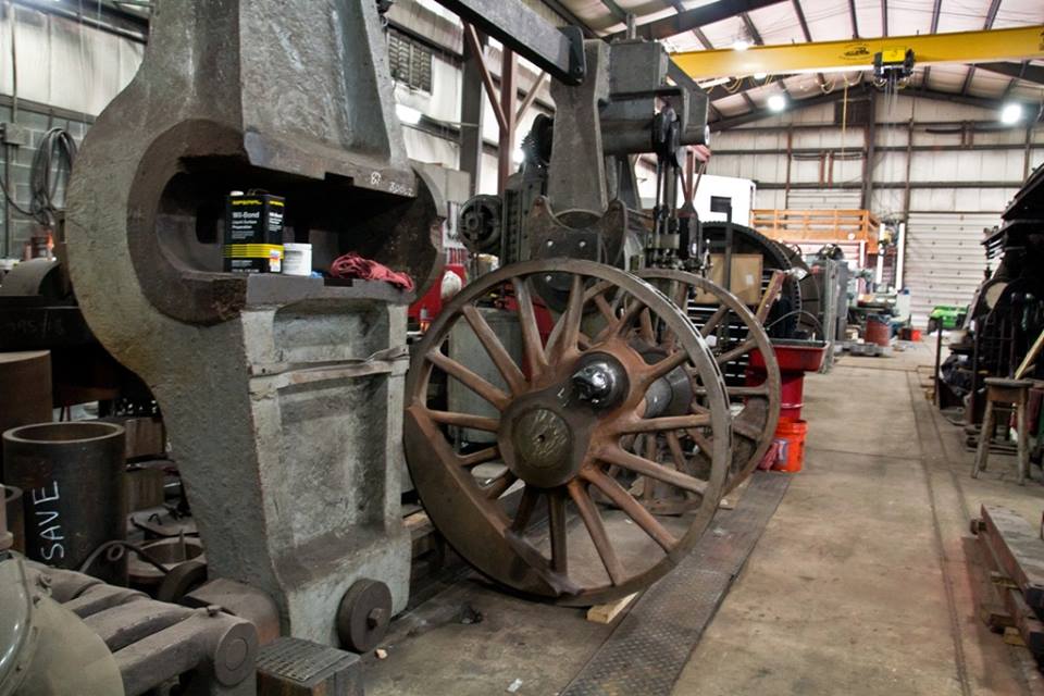
-
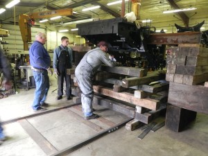
- Volunteers add cribbing under the CNW 1385. Photo courtesy SPEC Machine.
-
- Volunteer Richard Potthast operates a hydraulic jack to lift the CNW 1385 frame. Photo courtesy SPEC Machine.

Photographer Brian Allen was on hand the day the drivers were rolled under the frame. His Flickr album from the day can be seen by clicking the image below.
Upcoming Tasks
The steel side plates for the cab (where the locomotive lettering appears) were produced in October. With these in hand, it is possible to begin drilling holes into the wooden cab components for final assembly and painting. Cab repair and reconstruction is being carried out by CJ Woodworking at their facility with plans to move the finished cab, when complete, to SPEC Machine.
The other major component of the locomotive still ahead is the boiler. Currently 2D drawings are being converted into 3D CAD files which Deltak, the manufacturer of the new boiler, can then use for production. This work was previously being done by volunteer Jeff Westphal. Unfortunately, life can get in the way of volunteering and Jeff had to step down from this role. This and other delays have caused the boiler to not yet reach production stage at this time as was predicted earlier in the year. Despite this, progress on the 1385 as a whole continues at a steady pace. Once the drawings are complete, they will be sent to an independent third party for expert review before beginning production.
With boiler production nearing, your financial help is needed to allow work to continue at the steady pace enjoyed thus far. Gifts both large and small are vital to covering the cost of boiler production and remaining shop work to get C&NW #1385 under steam again. Visit the Donation page to learn how you can contribute toward the C&NW #1385 project.