↓
 

Mid-Continent Railway Museum

North Freedom, Wis.

Text: Mid-Continent Railway Museum. A historical and educational experience. Images of railway cars, people, and Mid-Continent logo.
  • Home
    • Home Page
    • News
    • Join Our Email List
    • Media
  • Plan Your Visit
    • Buy Tickets
    • Train Ride/Museum Info
    • Special Events
      • Autumn Color™ Weekend
      • Pizza Limited
      • Harvest Flyer
      • Pumpkin Special™
      • Root Beer Float Flyer
      • Santa Express™/Holiday Flyer
      • Stars and Stripes Special
      • Vintage Rail Car Tours
    • Cancellation Policy
  • Gift Shop
  • Restorations
    • Major Projects
    • Steam Status
      • Overview
      • C&NW #1385 Status Updates
      • Western Coal & Coke #1 Status Updates
      • Dardanelle & Russellville #9 Status Updates
    • Car Shop
      • General Updates
      • DSS&A Sleeper DULUTH
      • EJ&S #2
      • Badger #2
      • Copper Range #25
      • MLS&W #63
      • Copper Range #60
  • Equipment Roster
    • Equipment Roster Home
    • Steam Locomotives
    • Diesel/Other Locomotives
    • Wooden Passenger Cars
    • Steel Passenger Cars
    • Wooden Freight Cars
    • Steel Freight Cars
    • Cabooses
    • Service Equipment
    • Former Collection Items
  • Resources
    • Online Archives Home
    • Wooden Car Builders
    • MCRM Newsletters
    • Gazette Archive
    • Audio Archive
    • Video Archive
    • Wallpaper
    • Kids Page
      • Kids Page
      • What Makes A Diesel Locomotive Work?
      • What Makes A Steam Locomotive Work?
  • About Us
    • Contact Us
    • About Mid-Continent
    • Board of Directors
    • Department Leaders
    • Our Staff
    • Become a Member
    • Volunteer
    • Employment
    • Tour of Grounds
    • Local History
    • Mid-Continent Timeline
    • Privacy Policy
  • Donate

Tag Archives: firebox

Post navigation

← Older posts

C&NW 1385: Grate Little Follow-up

Mid-Continent Railway Museum Posted on April 15, 2022 by Jeffrey LentzApril 14, 2022

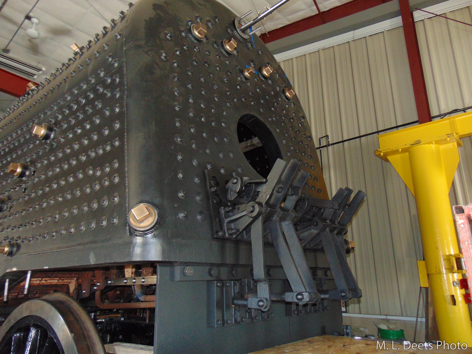
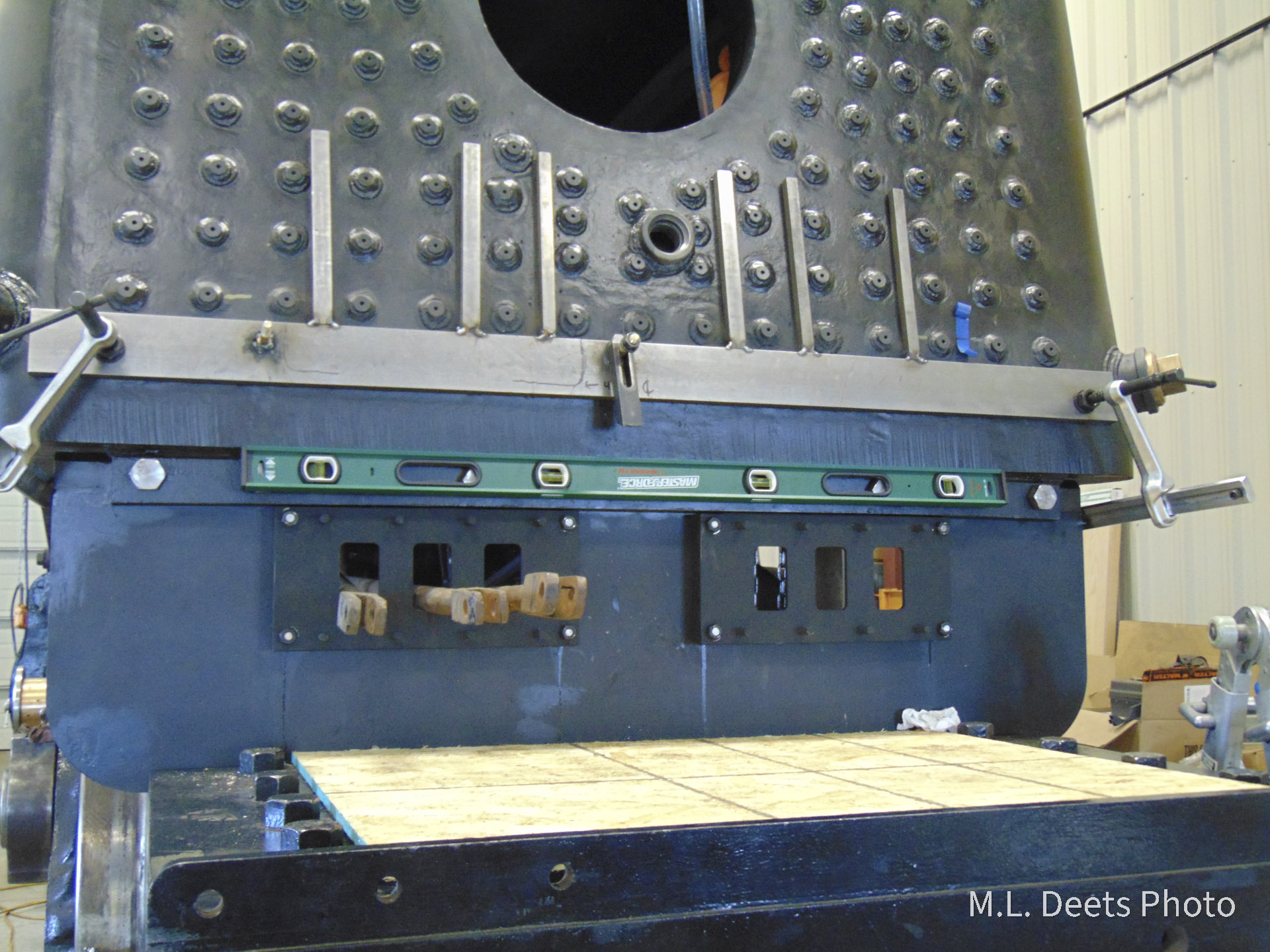
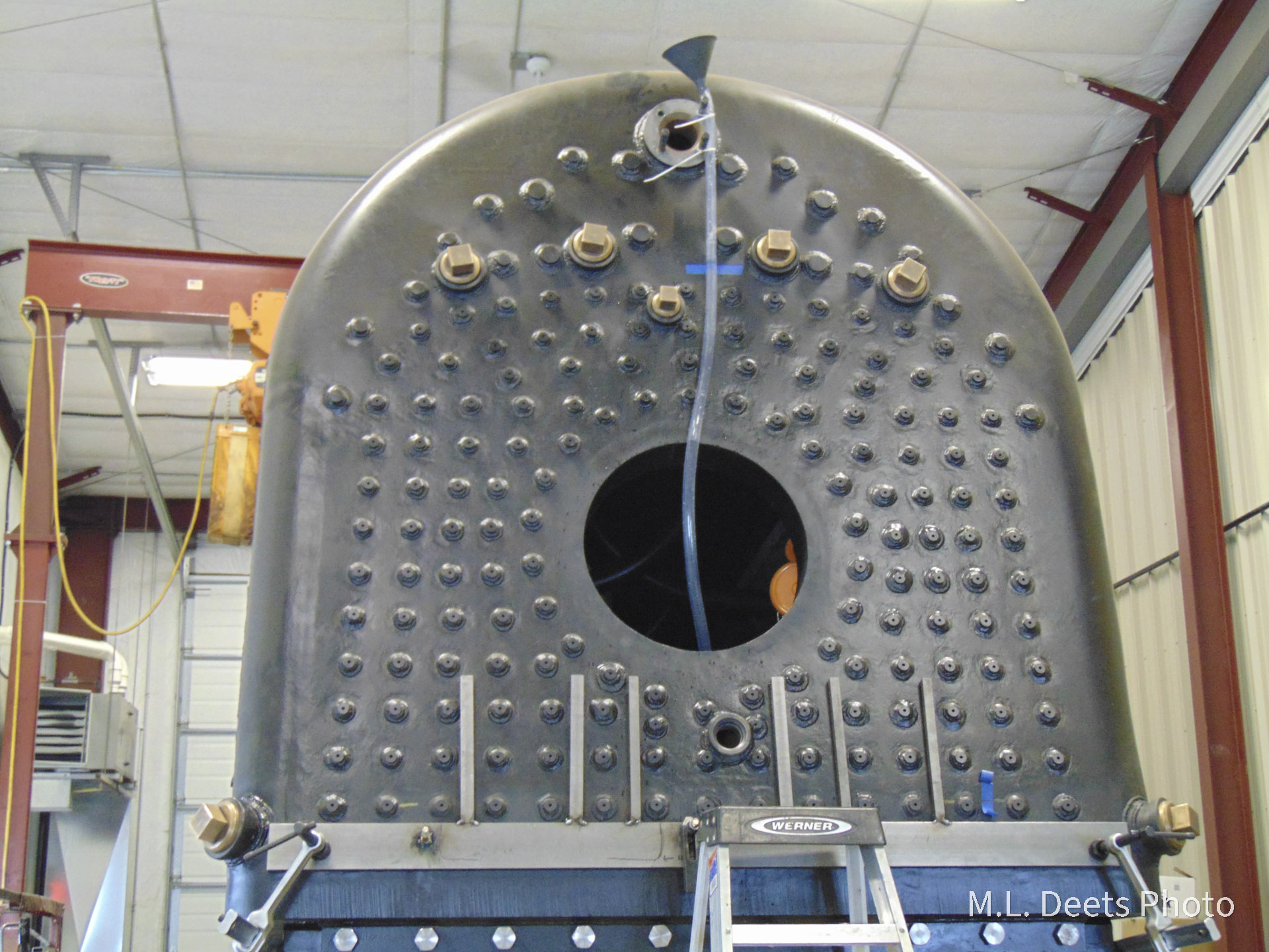
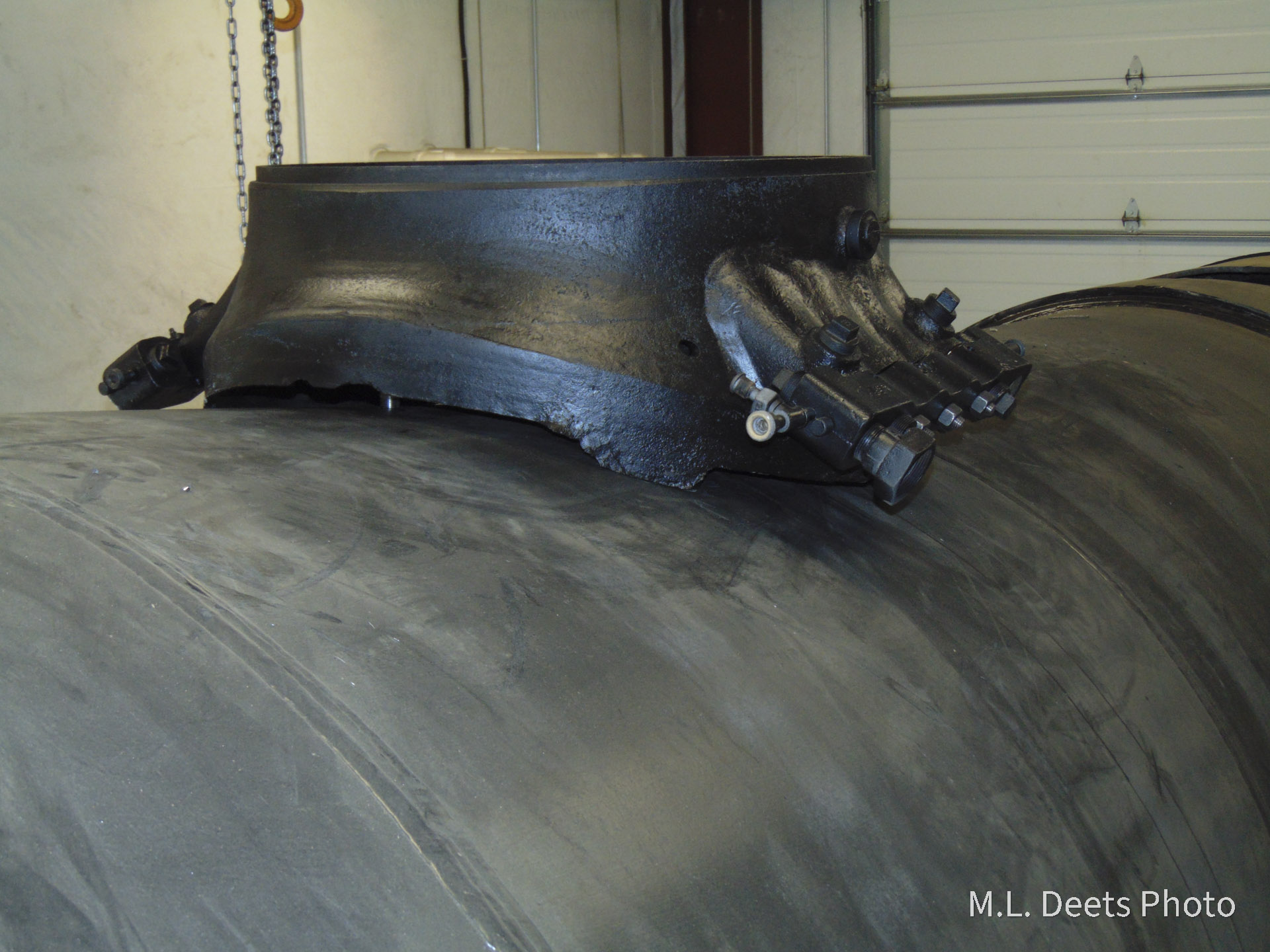
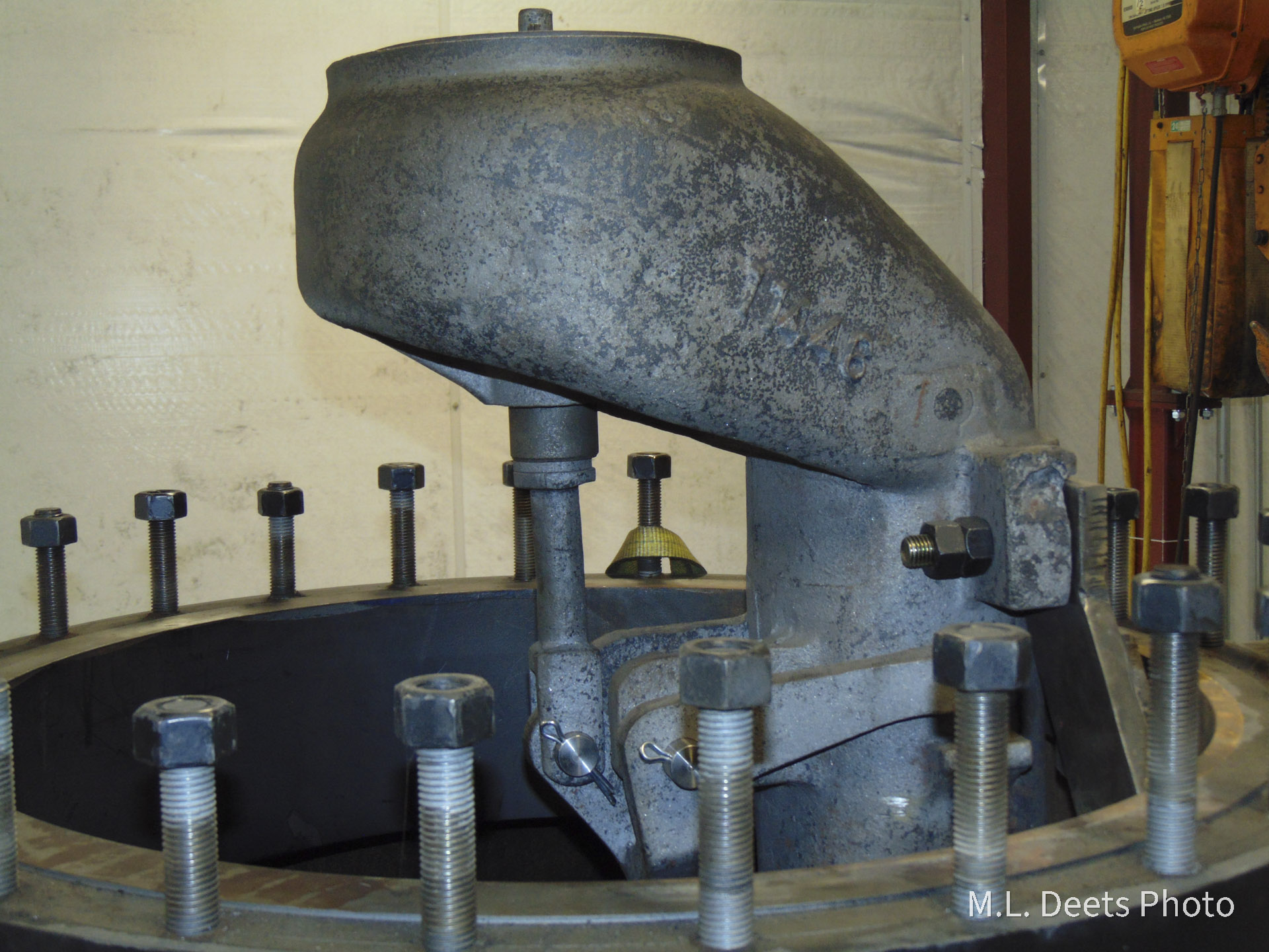
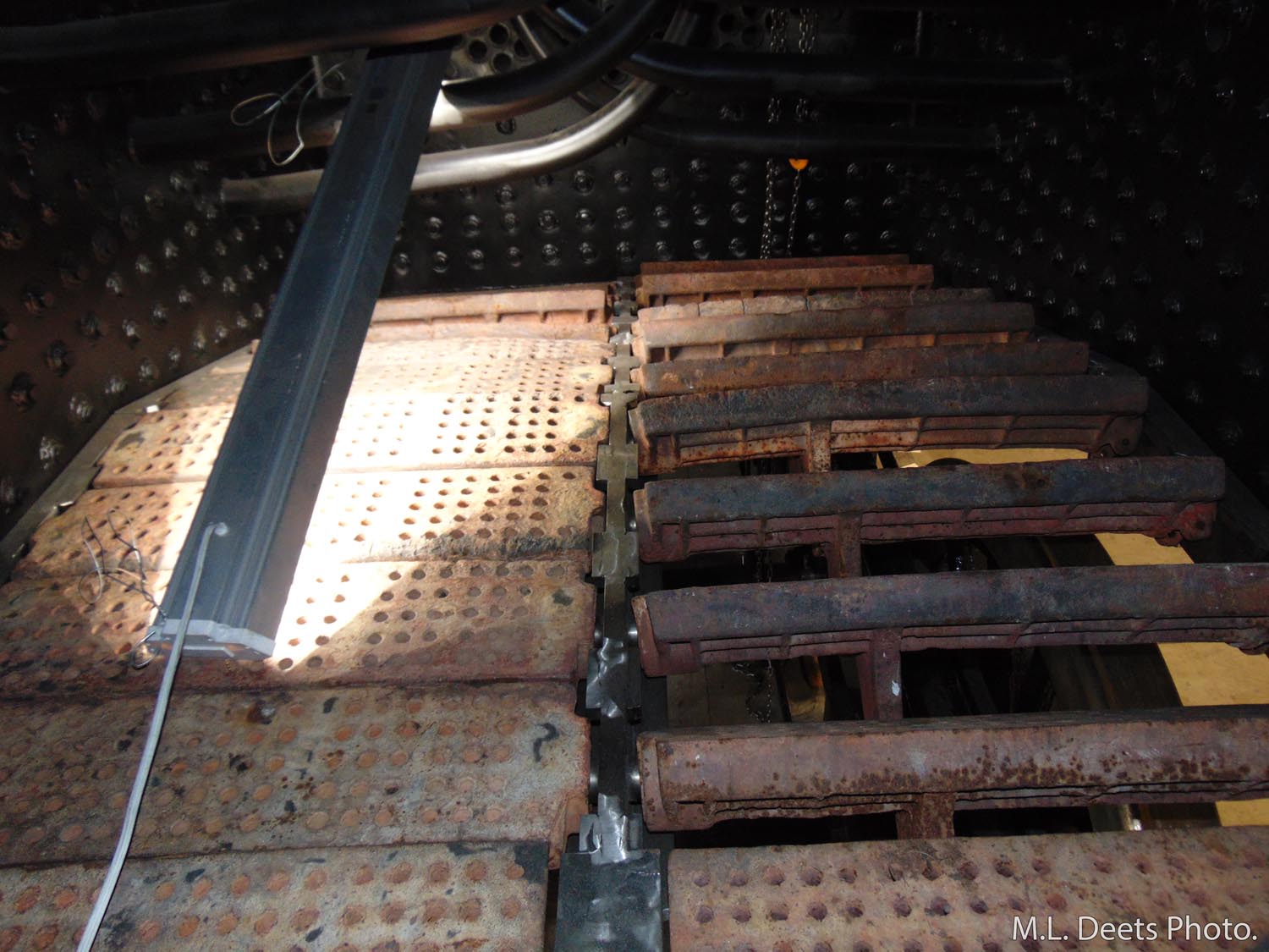
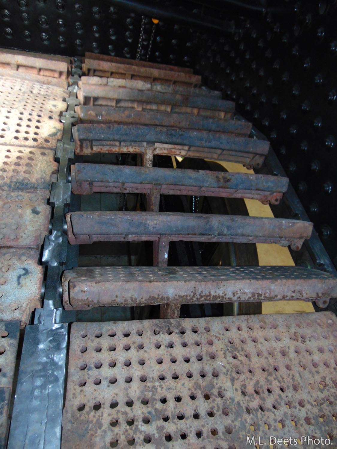
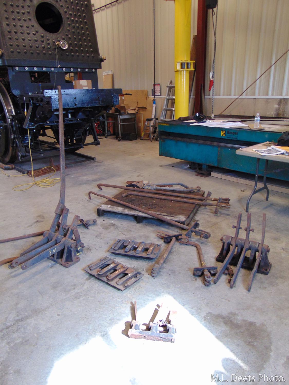
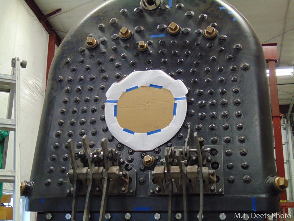
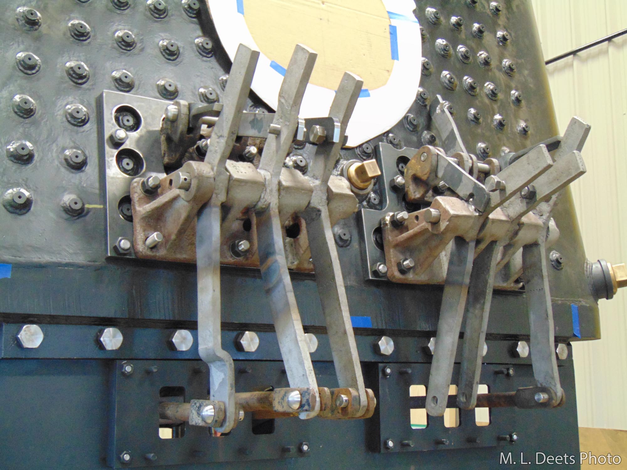
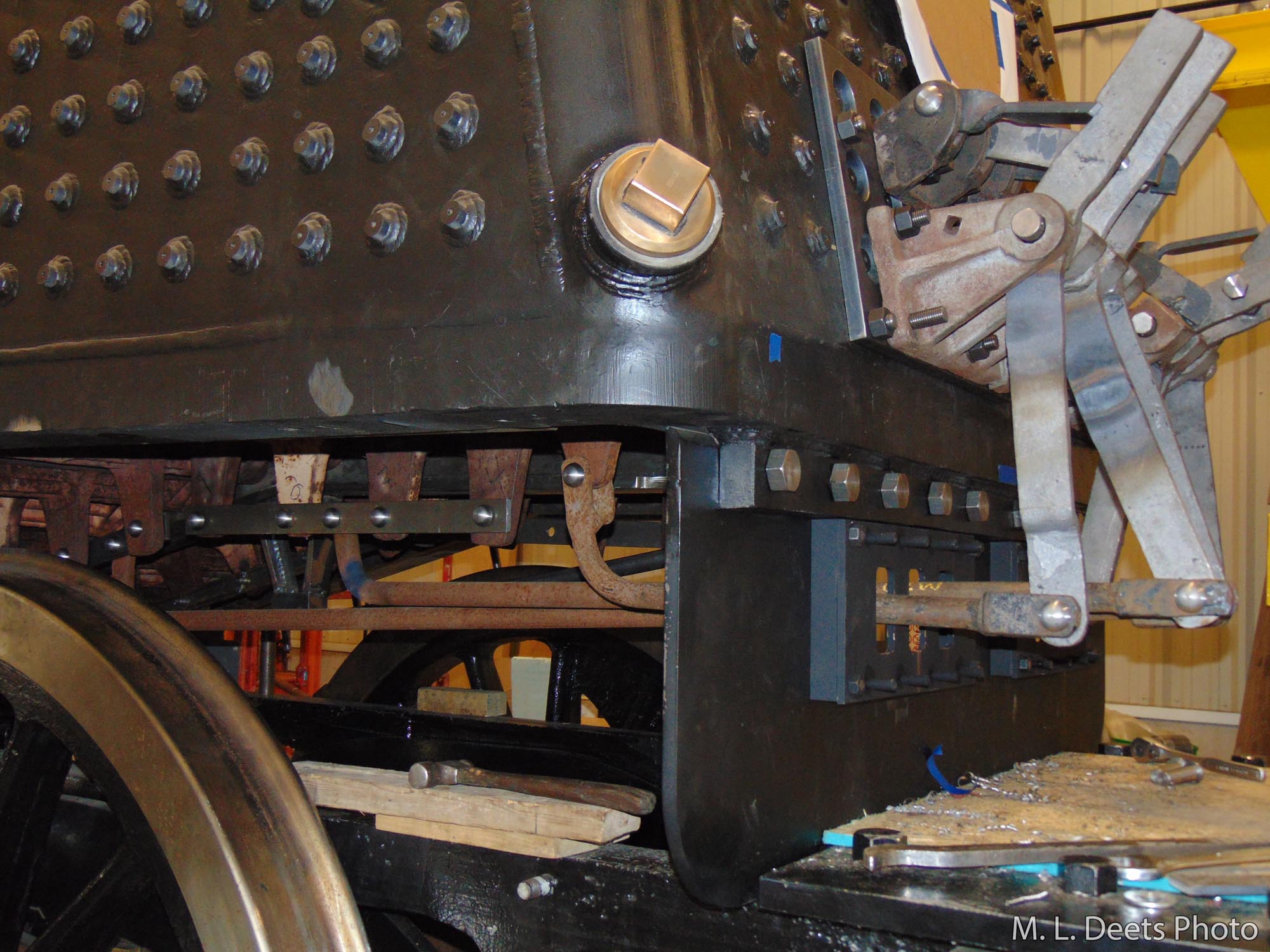
Our update of November ’21 covered what was going on with the grate installation inside the firebox. Here we will tie things up and cover the shaker mechanism & linkages. The shaker fulcrums are attached low on the backhead of the boiler near the mud ring. The cardboard over the firedoor hole is a mock-up for a needed spacer to allow mounting the firedoor over the staybolt ends. Detail on why is included below.

Firedoor spacer plate template.

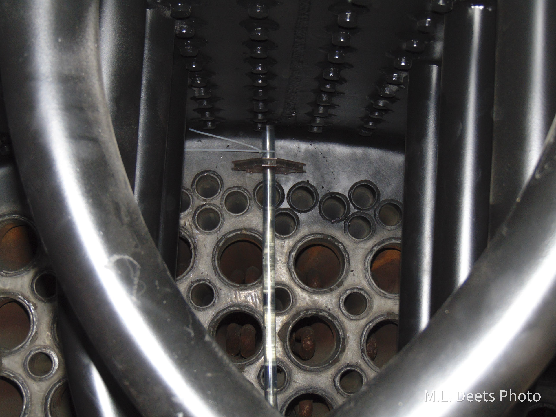
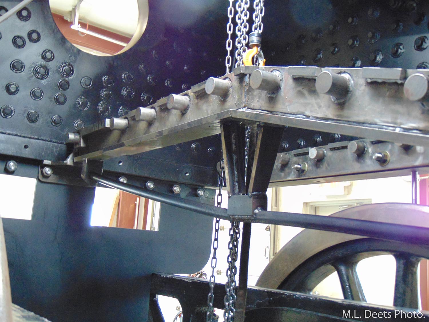
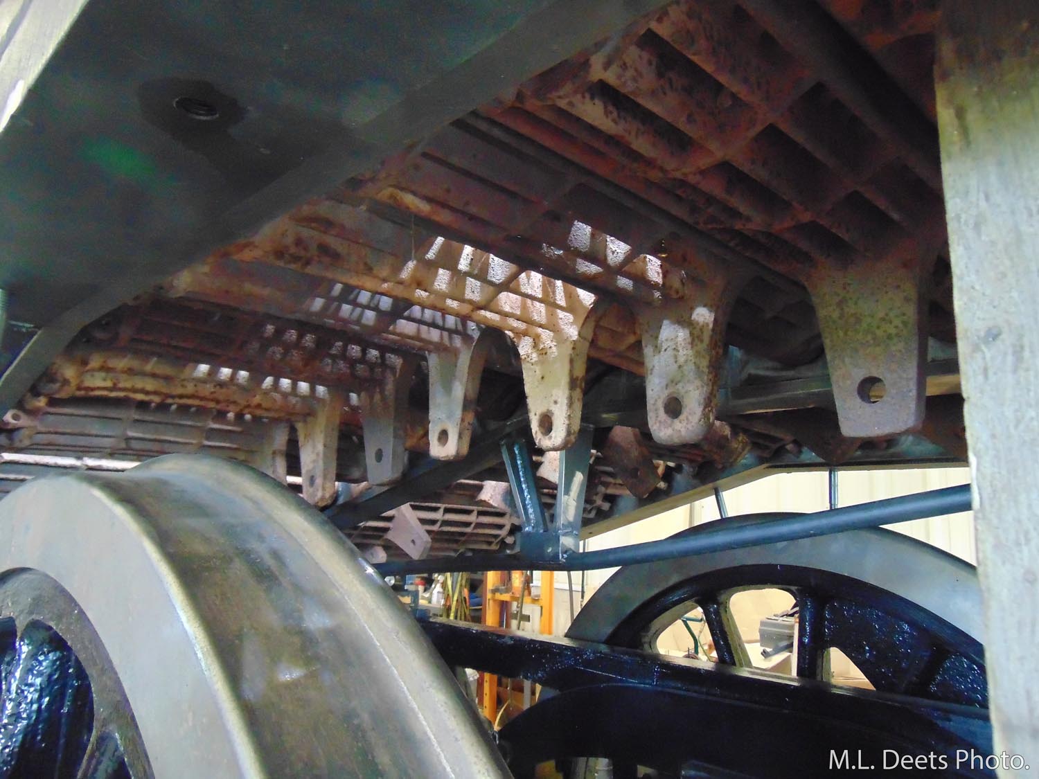
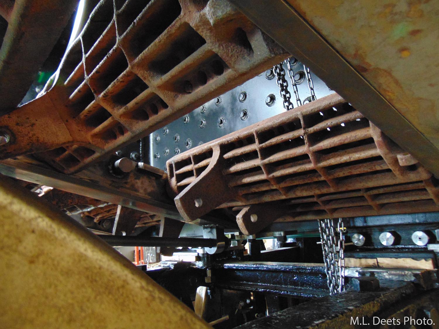
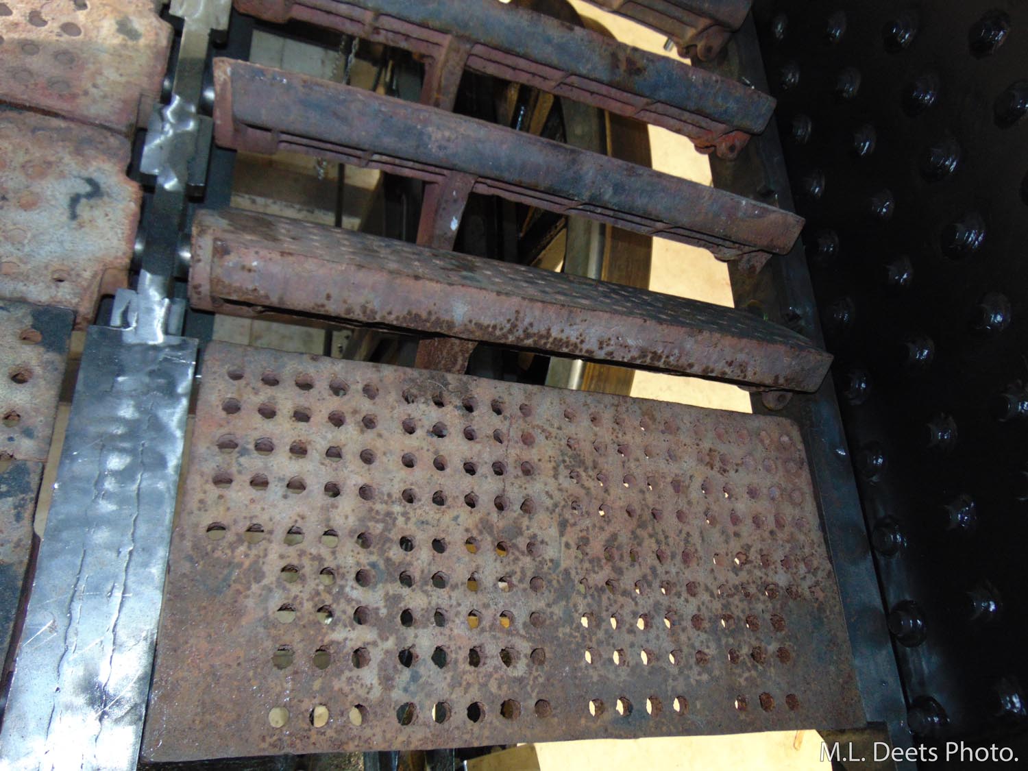
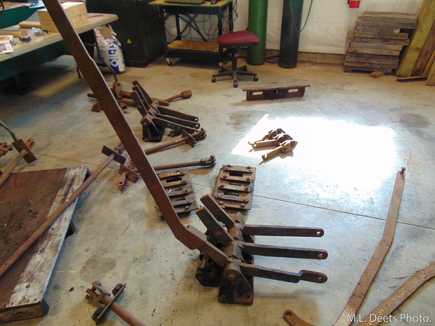
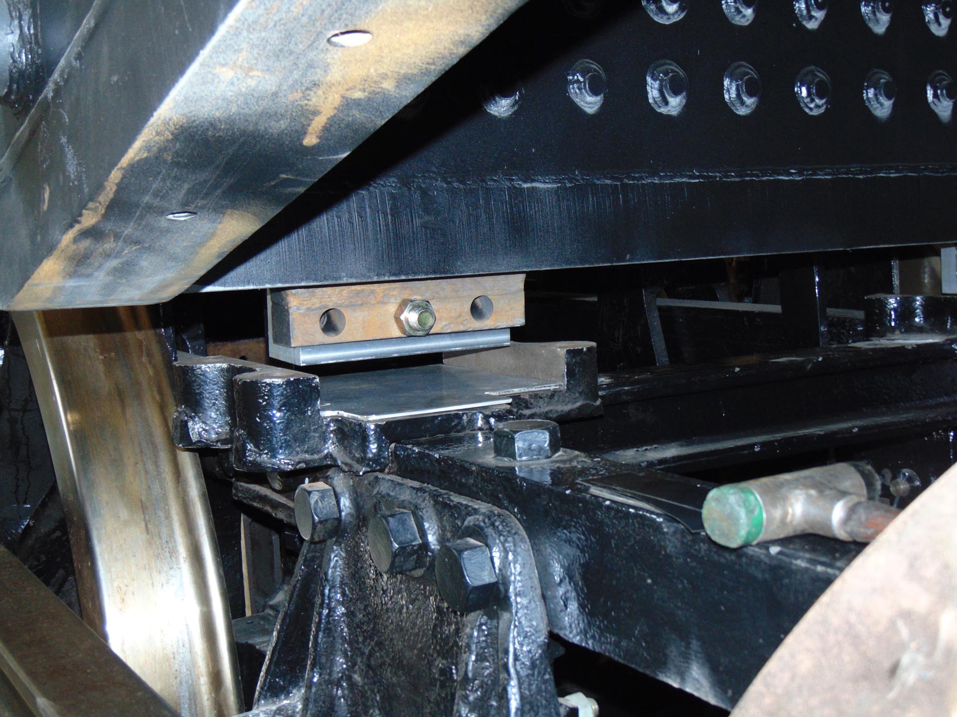
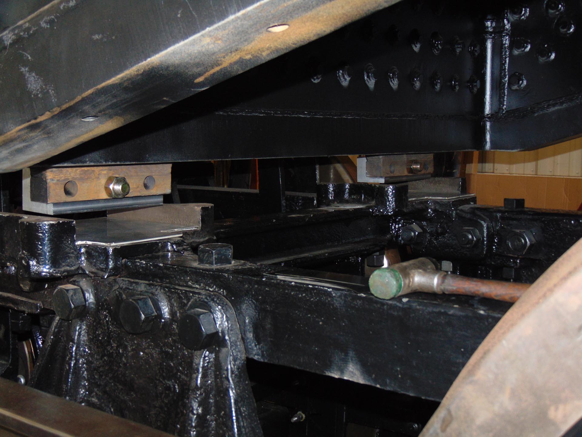
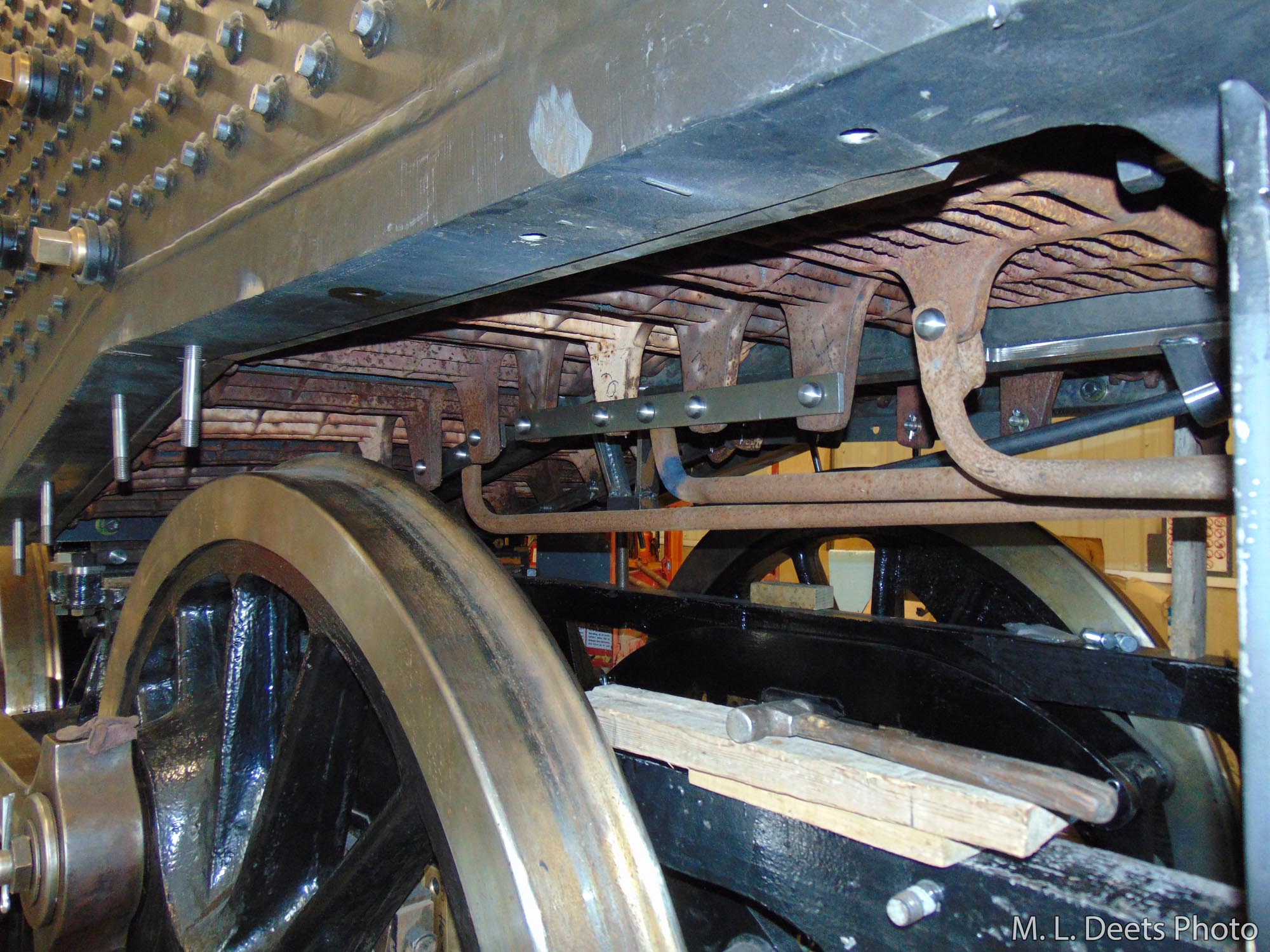
The shaker handle is slipped over the short stub controlling the section of grates to be shaken and the latch is released to allow the work to begin. The shaker rods reach under the boiler and connect to the tabs on the bottom of the grates in groups.

Grate shaker fulcrums.
Grate shaker linkages.
Firebox grates and grate shaker connections.

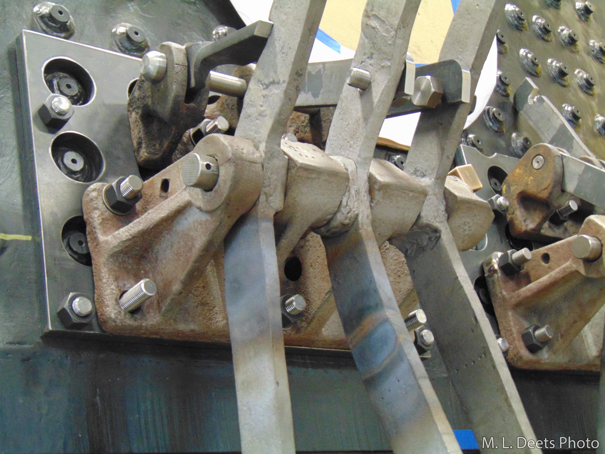
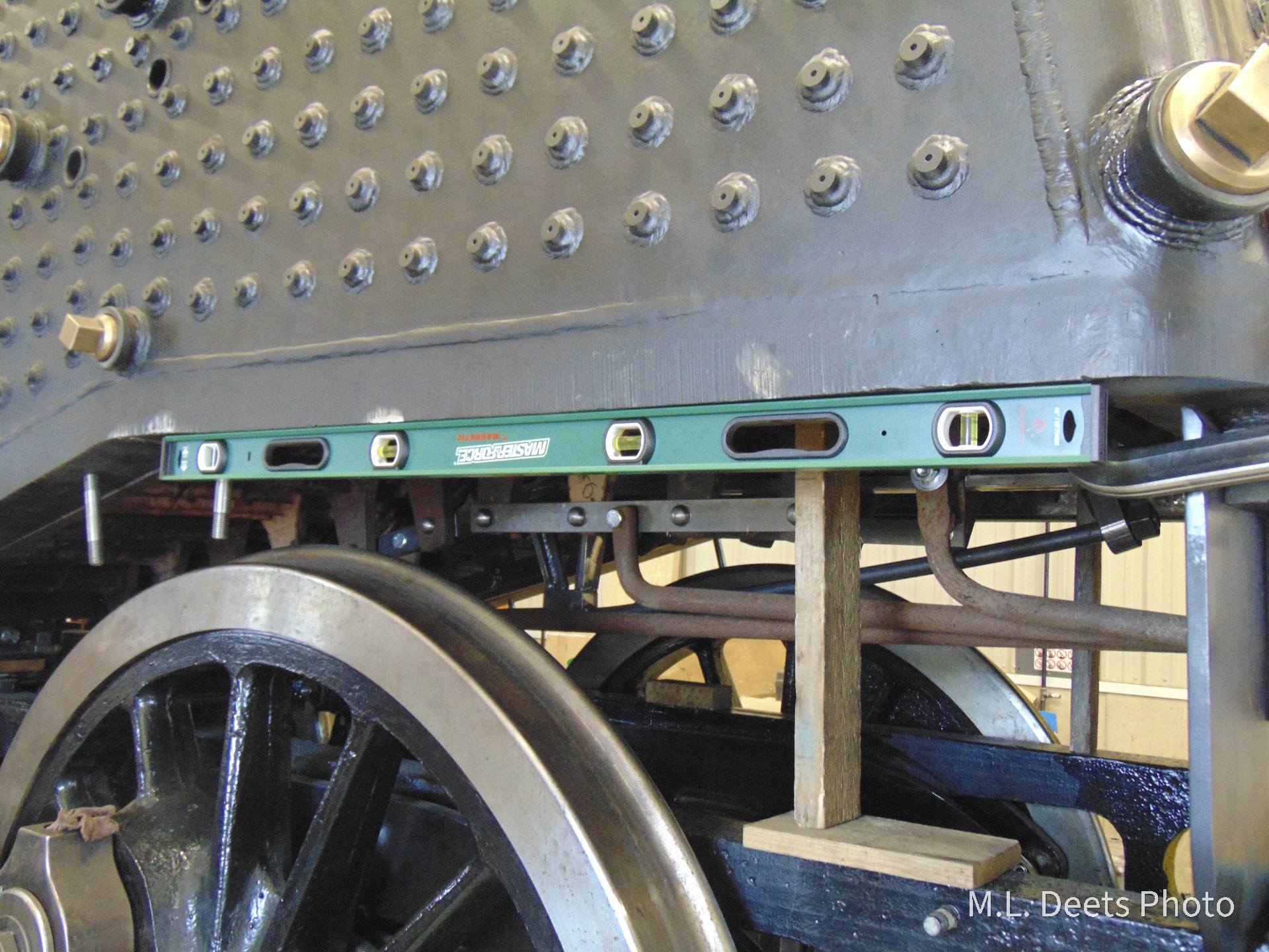
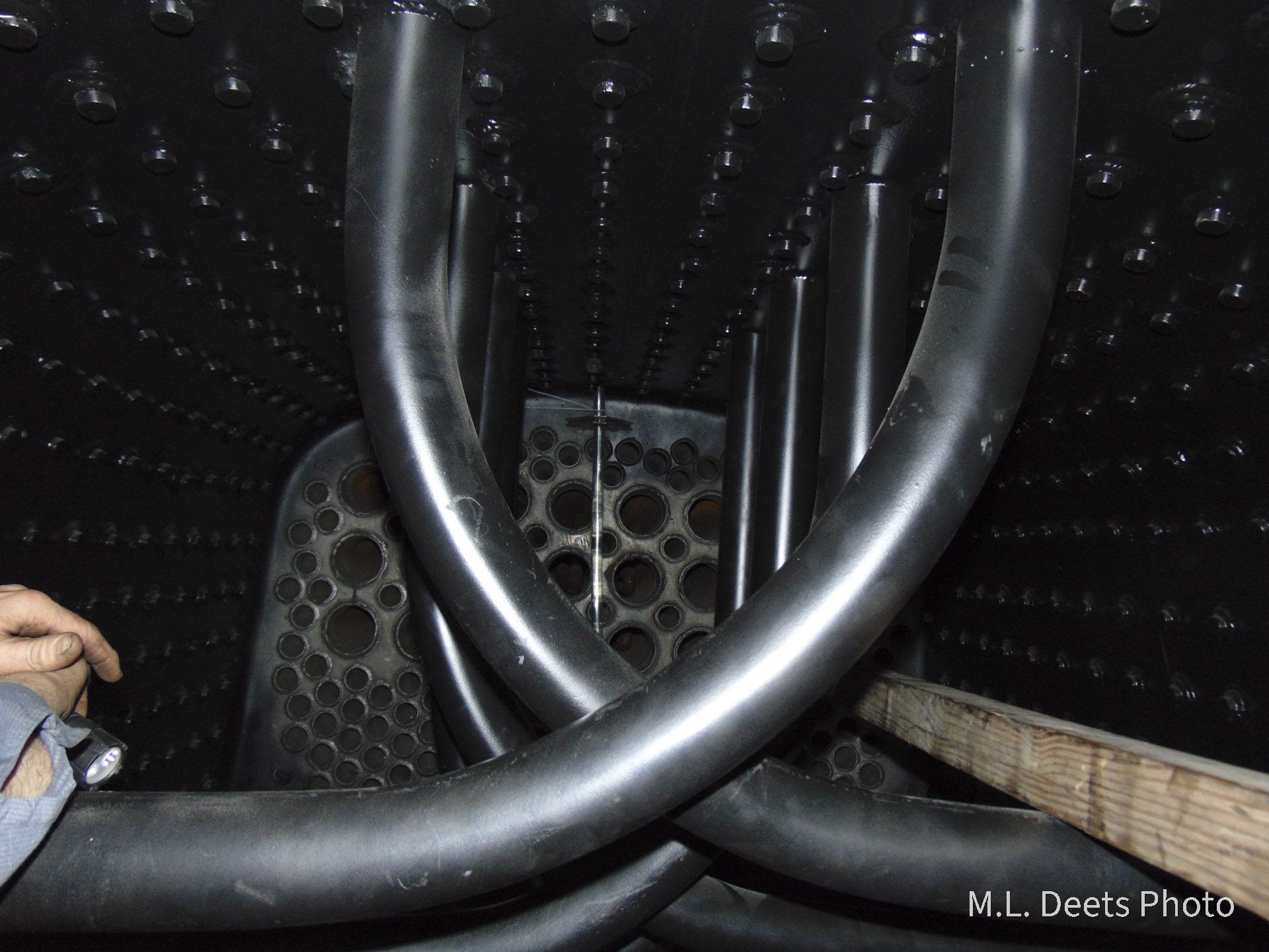
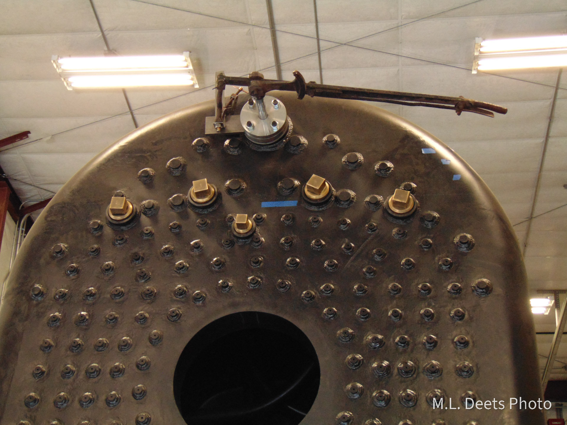
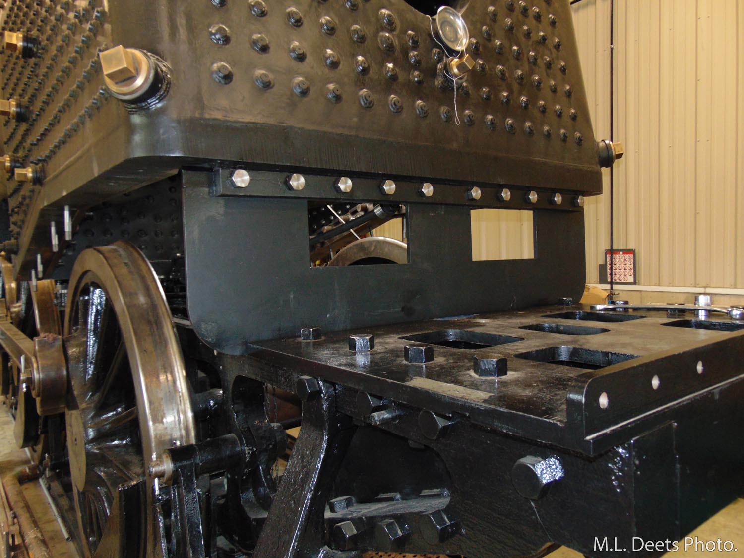
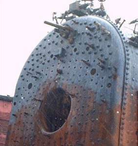
Because we are dealing with a new boiler of welded construction modifications are having to be developed and implemented. In the new boiler the welded staybolts stand out from the surface where the original construction used threaded stays which were hammered over during installation and resulted in an almost smooth backhead as seen in this shot from 2004.

C&NW’s old boiler with smooth backhead. 2004 photo.

A spacer plate has been machined in order to give a smooth mounting surface for the fulcrums and you can also see new pins and latches have been fabricated. In the last shot we can see the grate shaker system fully installed and ready for the first fire.

Detail of spacer plate for grate shaker fulcrum.
Fully installed grate shaker system painted and ready for use.
Tagged firebox

C&NW 1385 Update: On the Level

Mid-Continent Railway Museum Posted on February 12, 2022 by Jeffrey LentzFebruary 12, 2022

What are the first three things an operator must know on any boiler? 1) Where’s your water?, 2) Where’s your water?, And 3) Where’s your water?

A steam locomotive’s water level is so important the Federal Railroad Administration includes an entire section dealing with water gauges in the CFR Title 49 Part 230 Steam Locomotive Inspection and Maintenance Standards. Part of 230.51 states that “…The lowest reading of the water glasses shall not be less than 3 inches above the highest part of the crownsheet. …”.  What’s the crownsheet?  It is the ‘roof’ of the firebox so it will have the heat of the fire on one side and the water of the boiler on the other.

steam locomotive diagram showing location of crownsheet

The water is constantly absorbing the heat transferred through the crownsheet and keeping the steel relatively ‘cool’.  If the water were allowed to get low enough to let the crownsheet become dry then the heat of the fire from the underside could quickly damage the steel or worse.

How do we prevent this situation?  By constantly being aware of the water level in the boiler.  But first we must know how low is too low by knowing where the top of the crownsheet is.  This was done at SPEC Machine in January by first confirming the engine was setting level.  Front to back level was first checked and then side to side.

  • Level under 1385’s firebox verifying front-to-back level.
  • Closeup of side line level.
  • Second level to check side-to-side level under backhead.
  • Closeup of rear line level.

The next task was to use clear plastic tubing to create a “U” shaped tube open at both ends.  One end of the tube was placed against the highest point of the crownsheet inside the firebox but with a small notch in the end to allow air and excess water to escape.

  • Water-filled tube inside firebox as seen from firedoor.
  • Closer view of water-filled tube inside firebox. Note the superheater units visible within the flues.

The other end of the tube was brought out through the firedoor and tied to the throttle gland so the outside end would be higher than the end inside the firebox and a funnel was used to fill it with water.  Once the water quit running out of the end of tube in the firebox the level of the water shown at the outside end is equal to the level of the bottom or inside/fireside surface of the crownsheet. 

  • Water-filled tube coming out of firedoor and attached to backhead.
  • Masking tape line marking the height of the bottom, or “fire side” of the crownsheet.

To locate the top of the crownsheet and mark it per FRA requirements we had to add the thickness of the welds and the crownsheet itself.  Now that we’ve found the top of the crownsheet the water glasses and try cocks can be laid out for installation so the lowest water indication is no less than 3 inches above it.  Generally speaking as long as we can see water in the gauges we’ll have at least 3 inches of water over the crownsheet if we’re on level track.

Once finished playing in the water, other layout and installation steps have been made.  Locating and installation of the sand dome base has been finished and this task includes another milestone in the 1385 project; the first studs to be applied to the boiler since its delivery to SPEC Machine are used to hold the sand dome base in place.  You can even see the glint of one of the new studs at the top of the boiler and just under the edge of the base here.

  • Lookup up at the sand dome from floor level.
  • Installed sand dome. One of the new studs is visible.

Another fixture on the backhead is the throttle lever and the pivot point that is studded to the boiler.  Here Steve has rigged a temporary way to support the pivot to facilitate this layout.  The throttle rod reaches through the packing gland attached to the backhead and through the boiler to connect with the bell crank and levers that will allow the engineer to open and close the throttle which resides in the steam dome.

  • Throttle lever attached to backhead.
  • 1385’s throttle, located inside the steam dome.
Tagged crownsheet, firebox, sand dome, throttle

Wisconsin State Journal Visits SPEC Machine

Mid-Continent Railway Museum Posted on November 14, 2021 by Jeffrey LentzFebruary 12, 2022

The Wisconsin State Journal writer Barry Adams paid a visit to SPEC Machine to take a look at the latest progress on Mid-Continent’s Chicago & North Western #1385 steam locomotive and interviews shop owner Steve Roudebush.

NOTE: Article may require a subscription to Madison.com to access.

Go to Article
Tagged firebox

1385 Update: Grate Progress

Mid-Continent Railway Museum Posted on November 3, 2021 by Jeffrey LentzNovember 3, 2021

Progress continues on the grate bearers and grates for the #1385. As seen in the following photos, the center bridge has been completed as well as the Engineer and Firemans’ side outside bearers.  As will be shown in a moment the grates will be supported by the round pins on the bearers.

  • Installed grate bearer complete with pegs, plate along bottom, and bridge support pieces.
  • View of completed and installed center grate bearer and engineer-side grate bearer.

With the grate bearers now installed, efforts turned to the grates themselves. Looking from the Fireman’s side (see Grate Photo 1) almost all the grates have been put in place and are hanging from those pins. On the Engineer’s side one grate has been left out (see Grate Photo 2) to illustrate where the grates hang. It can also be seen how the grates pivot or rock on the pins to allow the crew to clean and manage their fire.

Looking in through the firedoor (see Grate Photo 3) at the left side you can see how the grates form a solid yet perforated floor to hold the fuel yet allow enough air up through the fire bed to promote complete & proper combustion. On the right side the grates are rocked forward to a degree that the fireman would be dumping the fire into the ashpan. This is done in the morning while cleaning the fire of yesterday’s ash while preparing for today’s fresh fire and another day of steaming. If the fireman simply needs to even out the fire or shake down some accumulated ash the grates can be rattled back and forth just a small amount. This will cause the ash to fall down into the ashpan through the holes in the grates.

  • Grate Photo 1: View of grates from underneath the firebox, observed from fireman side.
  • Grate Photo 2: View of placed grates, observed from engineer side. One grate removed for better view.
  • Grate Photo 3: View of grates looking through the fire door.
  • Grate Photo 4: Detail view of grates on engineer side. Some warping is visible.
  • Grate Photo 5: Large “dump grate” located closest to fire door.


You can see in the photos we are using “experienced” grates. A few are bowed due to poor ashpan management causing excessive heat and causing the grates to warp. Here is a more detailed shot (Grate Photo 4) of the open grates and the large “dump grate” at the bottom of the photo.

The dump grate (Grate Photo 5) is closest to the firedoor and is about the size of two of the other grates. It pivots not in the center but along the edge closest to the firedoor and as the name implies is used to dump a large amount of either ash or fire as needed into the ashpan.
The grates are divided into three sections looking back to front in the firebox and there is the fireman’s set and the engineer’s set. The large tabs that extend down from the bottom of each grate are connected by a series of tie bars, pins and levers to the grate shaker fulcrums in the cab.

At the time the photos were taken, the shaker arrangement was being laid out on the floor for evaluation of the extent of needed repair/replacement of parts. The shaker fulcrums and latches will be mounted to the boiler and some of the other parts will get mounted to the rear boiler support which has also been newly installed.

  • Grate shaker mechanism.
  • Grate shaker mechanism.
  • Newly installed rear boiler support.


Bit by bit the puzzle pieces are finding their way back together to form a living, breathing iron horse and soon #1385 will again be the Whistle on the Wind!

Tagged firebox

Catching Up with 1385

Mid-Continent Railway Museum Posted on July 20, 2020 by Jeffrey LentzOctober 28, 2020

In the shadow of the COVID-19 pandemic and its resulting shutdowns over the past few months, we have been fortunate SPEC Machine has been able to work on the Chicago & North Western #1385 at all. Many of the things done during this time period has been measuring, fitting and design work that provides little to no visual change to the locomotive which makes progress reporting a bit more difficult. 

That said, the boiler and smoke box have been positioned which allows for the furnace bearers to be made. The boiler is fixed solidly to the smokebox and cylinders but like so many other things, steel expands as it gets hotter.  When the 1385 is fired up it will start at ambient temperature but when it reaches a full head of steam of 200 PSI the boiler will be about 388° F.  This will cause the boiler to grow in length.

To accommodate this, the rest of the boiler and the front corners of the firebox rest on a pair of bronze shoes called furnace bearers. The shoes bolt to tabs welded to the front-bottom of the mudring. These shoes allow the boiler to freely expand and contract as needed while still being supported by the locomotive frame.

Animated illustration of boiler movement

The below photos show the tab as well as the top part of the shoe holder that will support the weight of the boiler.

Detail view of furnace bearer. Pete Deets photo.

View of furnace bearer. Pete Deets photo.

View of both furnace bearers. Pete Deets photo.

On the fundraising front, the 1385 project was recently the recipient of a $7,000 donation from the Bluewater Michigan Chapter of the National Railway Historical Society. While this is good news for the 1385, it sadly was donated as part of the Chapter’s dissolution and distribution of assets. The Bluewater Chapter was established in 1982 and was well known in railroad circles for operating many successful mainline passenger excursions around the Midwest, helping to bring railroading to the public. The Chapter faced tough times in recent years as mainline excursions became more challenging to operate for a variety of reasons, ultimately leading the group to dissolve the Chapter last year. We salute the Bluewater Chapter members for their amazing work over the years and are appreciative of this final act of generosity toward Mid-Continent’s 1385 program.

Tagged boiler, firebox, mud ring

Post navigation

← Older posts
QUICK LINKS
PLAN YOUR VISIT
BUY TICKETS
GIFT SHOP
DONATE
JOIN OUR EMAIL LIST
VIEW WEBCAMS
Live view of North Freedom depot

Contact Us

Mid-Continent Railway Museum
P.O. Box 358
E8948 Museum Road
North Freedom, WI 53951
Office phone: 608-522-4261
or 800-930-1385
E-mail: inquiries@midcontinent.org

Recent News

  • “Last Spike” Ceremony
  • Engine House Track #2 Update
  • 1385 Steam and Air Line Installation/Donation Update
  • #1385 Cab, Smoke Stack, and Hand Rail Installation/Donation Update
  • Your Help is Needed to Bring the C&NW #1385 Home Again!
©2025 - Mid-Continent Railway Museum - Weaver Xtreme Theme Privacy Policy
↑