Mid-Continent Railway MuseumPosted on by Jeffrey Lentz
Work on C&NW 1385’s three sets of 63-inch driving wheels continues. Work is being carried out by the Strasburg Rail Road shop facility in Pennsylvania. Here is a run-down of the status of the drivers as of an October 13, 2014 communication from Strasburg to Mid-Continent’s 1385 Task Force:
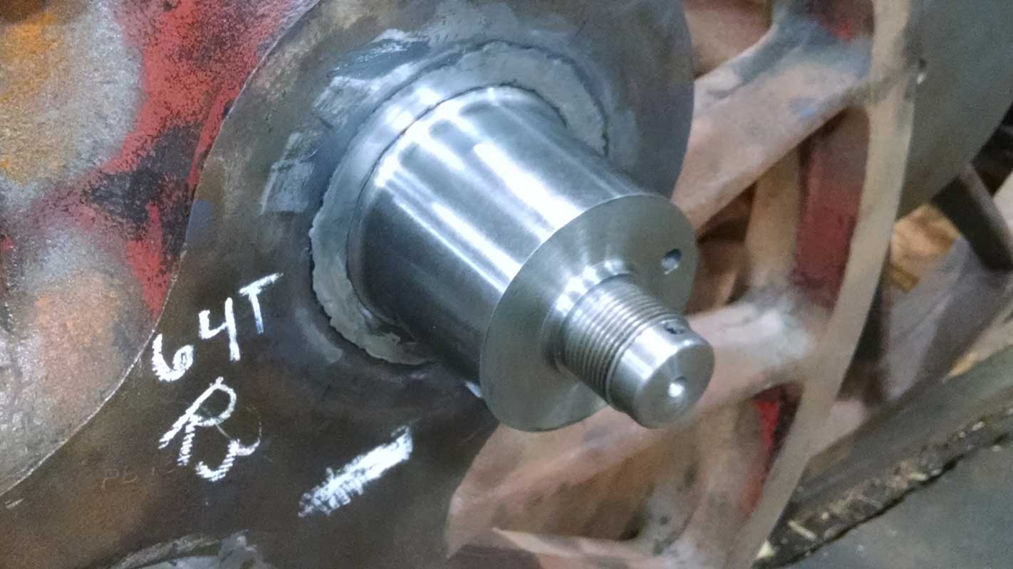
The #1 driver crankpins are turned and only in need polishing.
The #3 driver crankpin hub faces are welded up.
The new R3 crankpin (#3 driver, engineer side) is pressed in and ready to be riveted over on the back side.
The old R2 hubliner (#2 driver, engineer side) has been removed, its mounting studs are center punched, and ready to be drilled out. New hubliner material is on hand.
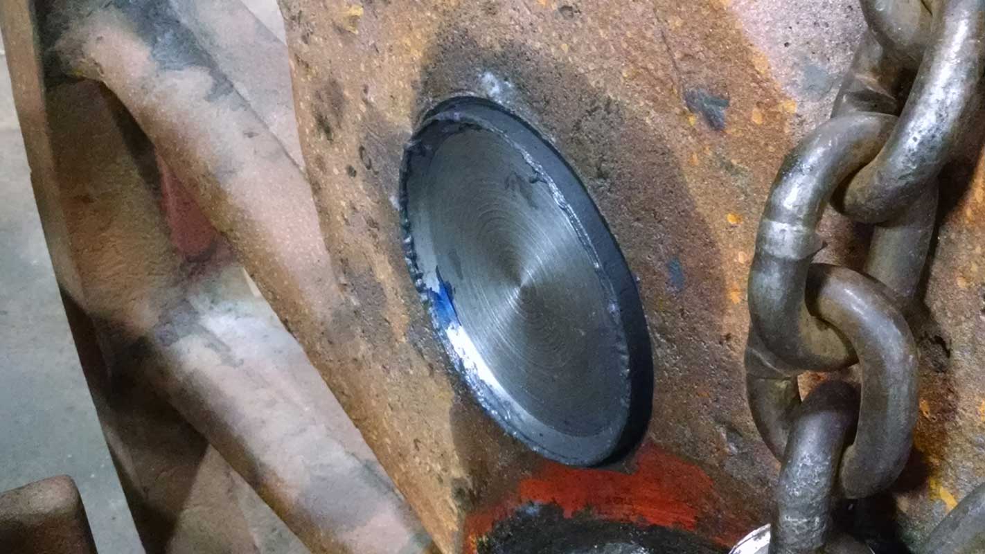
A crack near the R2 crankpin hub has been chased out and welded up.
The R2 crankpin hole has been bored out.
The new R2 crankpin is being machined.
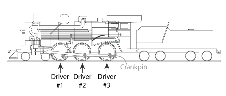
Diagram showing driving wheel arrangement on a R-1 class steam locomotive. Driving (powered) axles are numbered front-to-back and specific wheels on the axles are defined as being on the left or right side. For example, L3 refers the wheel on the left side (fireman side) of the third powered axle.
The estimated completion date for the driving wheels is the end of 2014. The biggest influence of whether the target will be met is uncertainty of the lead time for the delivery of new tires. The order of operations is to press all new crankpins in, then turn the tire seats on the wheel centers. The new tires will then be ordered to fit snugly to the final dimensions of the wheel centers.
See the March 30, 2014 post for a further explanation of wheel centers and tires.
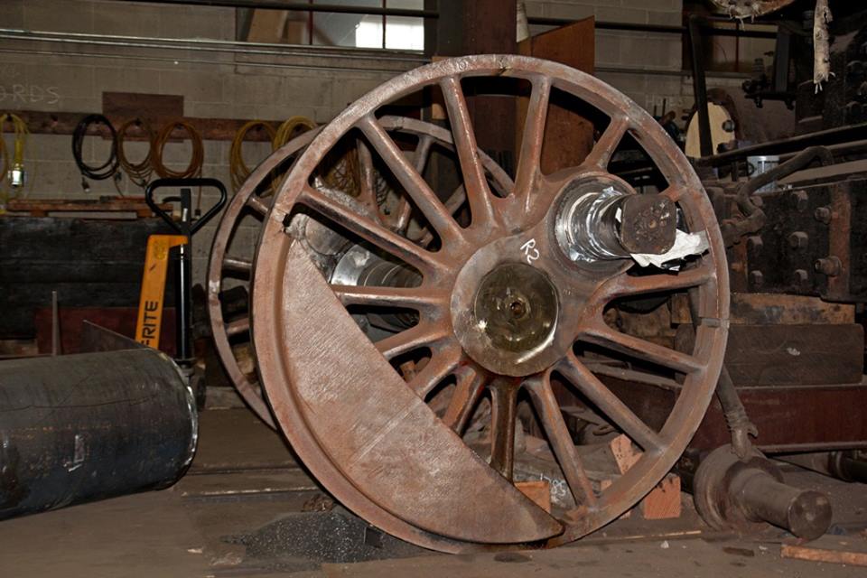
C&NW #1385 driving wheel repairs at Strasburg Rail Road.
C&NW #1385 driving wheel repairs at Strasburg Rail Road.
C&NW #1385 driving wheel repairs at Strasburg Rail Road.
C&NW #1385 driving wheel repairs at Strasburg Rail Road.
Mid-Continent Railway MuseumPosted on by Jeffrey Lentz
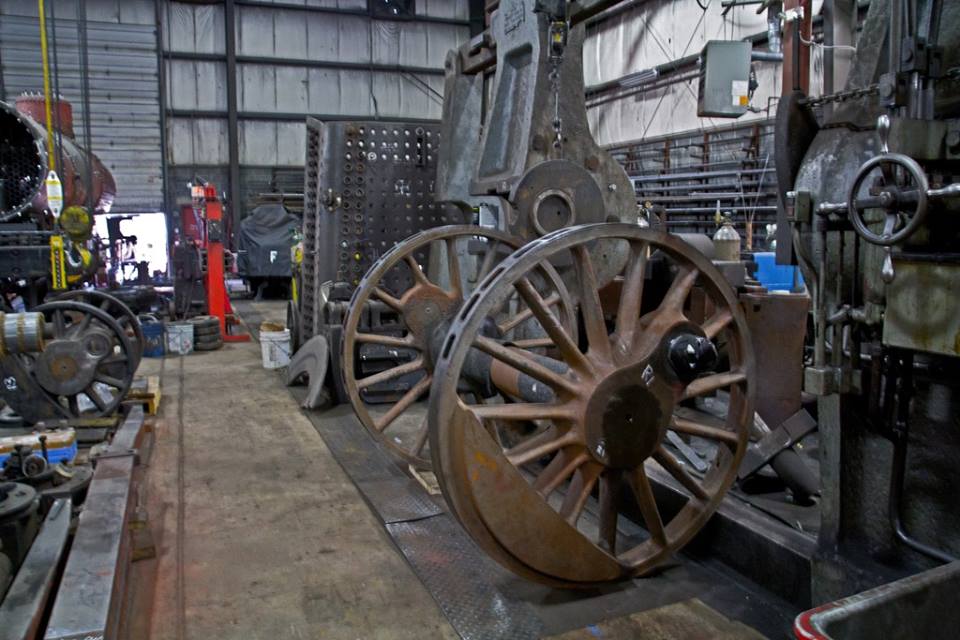
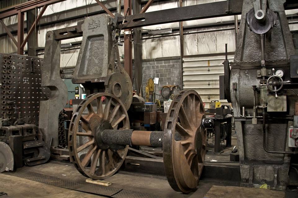
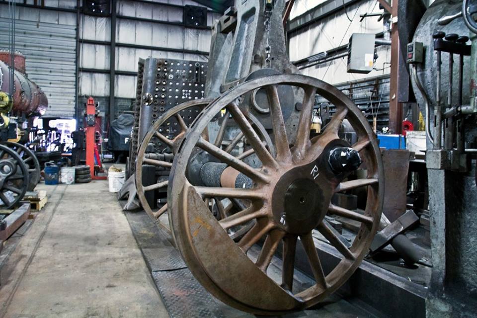
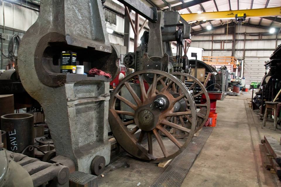
On March 30, 2014, C&NW 1385’s three sets of 63-inch driving wheels were shipped from Wisconsin to the Strasburg Rail Road in Pennsylvania in order to be “turned” on a lathe, receive new tires, and have other adjustments and repairs completed (scroll down to the March 30th post for additional detail). On the weekend of June 28, 2014, Mr. Bernard Krebs of Jim Thorpe, PA photographed the drivers for the benefit of this steam status page, allowing us a glimpse of the work in progress.
C&NW #1385 driving wheels at Strasburg Railroad. June 28, 2014. Bernard Krebs photo.
C&NW #1385 driving wheels at Strasburg Railroad. June 28, 2014. Bernard Krebs photo.
C&NW #1385 driving wheels at Strasburg Railroad. June 28, 2014. Bernard Krebs photo.
C&NW #1385 driving wheels at Strasburg Railroad. June 28, 2014. Bernard Krebs photo.
C&NW #1385 driving wheels at Strasburg Railroad. June 28, 2014. Bernard Krebs photo.
C&NW #1385 driving wheels at Strasburg Railroad. June 28, 2014. Bernard Krebs photo.
C&NW #1385 driving wheels at Strasburg Railroad. June 28, 2014. Bernard Krebs photo.
C&NW #1385 driving wheels at Strasburg Railroad. June 28, 2014. Bernard Krebs photo.
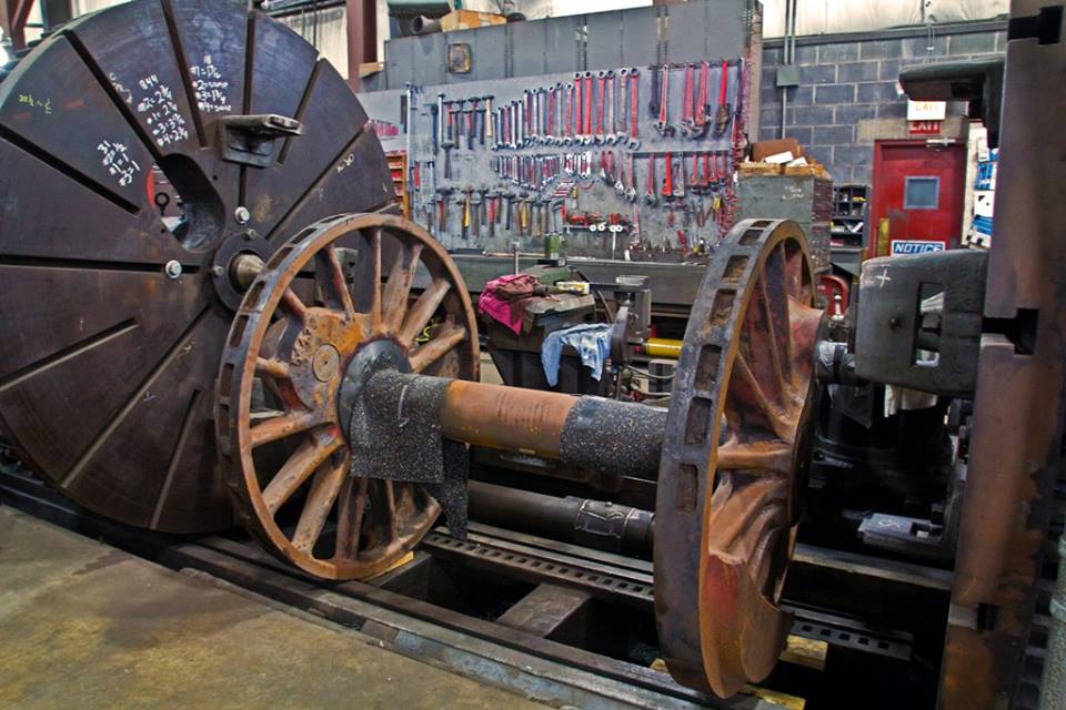
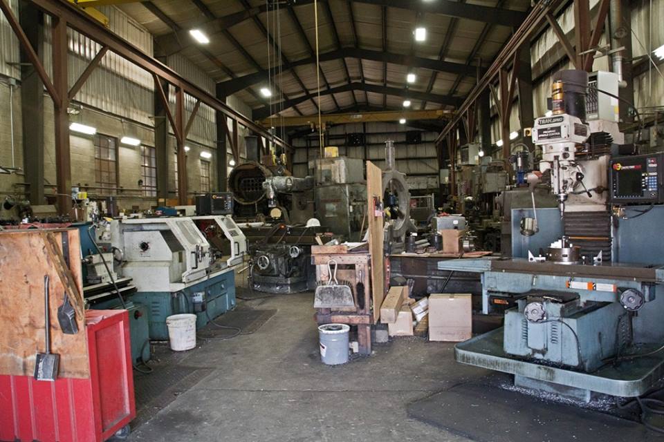
Strasburg Rail Road makes use of a 90-inch Niles wheel lathe originally sold to the Lehigh Coal and Navigation Company in 1912. Lathes of such sizes were commonplace in the major railroad shops of America when enormous steam engines commonly roamed the rails, but now are rare with a limited number of shops around the country capable of handling tasks of such size.
Modern railroad equipment still undergoes similar maintenance procedures but all feature smaller wheels. The electric traction motors used on modern locomotives make wheel size relatively unimportant compared to steam locomotives where wheel diameter directly impacted piston speeds.
During each full rotation of a driving wheel on a steam locomotive the piston and connecting rods change direction of motion twice (forward then back). This very rapid change of direction puts a large amount of stress on the parts involved. Therefore, increasing the distanced traveled per wheel revolution and thus reducing the number of back-and-forth piston motions per second was an important design feature for high speed operations. It is no coincidence that the Milwaukee Road Class A and Class F7‘s that were built for 100 MPH-plus running of the Hiawatha trains between Chicago, through nearby Wisconsin Dells, and on to the Twin Cities featured massive 84-inch driving wheels. The British LNWR 2-2-2 3020 Cornwall is an extreme example of this concept, featuring 96-inch driving wheels.
Per Wikipedia, “Freight locomotives generally had driving wheels between 40 and 60 inches in diameter; dual-purpose locomotives generally between 60 and 70 inches, and passenger locomotives between 70 and 100 inches or so.” Compare C&NW 1385’s drivers with those of Saginaw Timber Company No. 2 as an example. In order to attain a speed of 60 MPH, No. 2’s 44-inch drivers would require roughly 7.6 revolutions per second while No. 1385, built for fast freight and secondary passenger service, features 63-inch drivers that would require roughly 5.3 revolutions per second. Worded differently, it means the 1385 can travel 30% farther using the same number of piston motions. The Class A or Class F7’s 84-inch drivers meanwhile would only require a comparatively leisurely 4 revolutions per second.
Mid-Continent Railway MuseumPosted on by Jeffrey Lentz
Chicago & North Western No. 1385 turns 107-years-old today! That is worthy of celebration with a new steam status update.
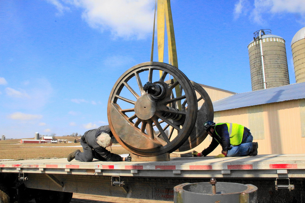
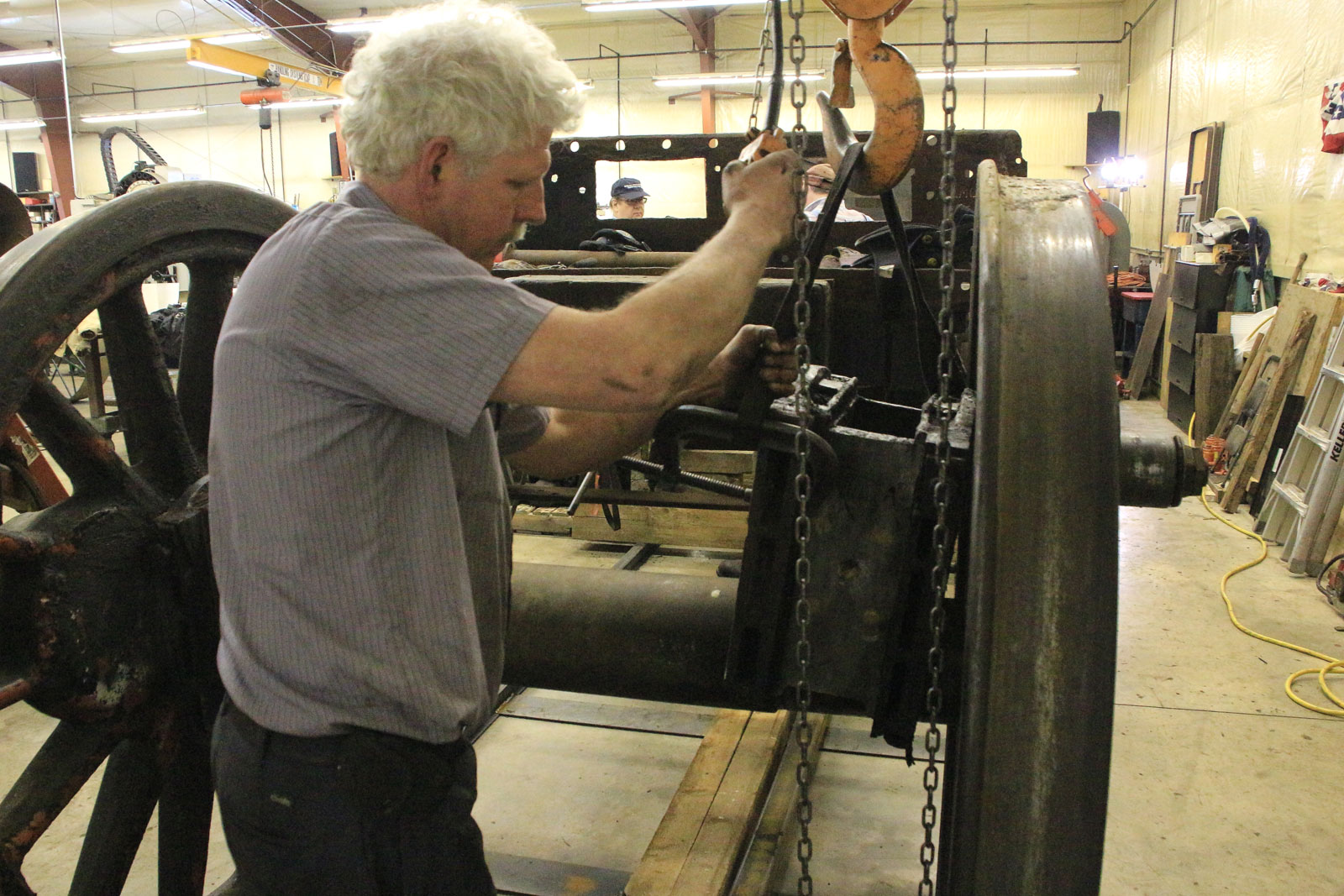
The reach of the restoration work on Chicago & North Western No. 1385 is expanding. Restoration work on various parts of the locomotive has already or is anticipated to take place in shops in Middleton and Fond du Lac, Wisconsin as well as Plymouth and St. Paul, Minnesota. Now components of Mid-Continent’s star locomotive will be traveling even farther from home for restoration work. On Monday March 24, 2014, 1385’s 63-inch driving wheels were loaded on to a semi-trailer for shipment to Strasburg, Pennsylvania. Upon arrival the drivers will again be inspected and a repair plan will be finalized with one of the nation’s premier steam restoration shops, the Strasburg Rail Road.
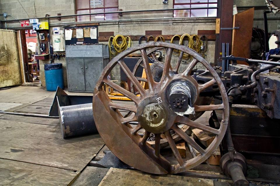
Driving wheels are usually designated by number, counting upward while moving from the front of the locomotive back toward the cab. A specific wheel can be designated by referring to it as the right side (engineer‘s side) or left side (fireman’s side). For example, No. 1 driving wheel, right side would be the driving wheel farthest forward on the engineer’s side. Simply referring to the No. 1 driver usually infers the wheels on both sides plus the connecting axle. The No. 1 and No. 3 drivers on the 1385 each weigh about 10,000 lbs. The No. 2 driver is the main driver, meaning it is the driver connected to the pistons providing the power. The No. 1 and No. 3 drivers are not directly connected to the pistons but are instead connected only to the main driver via connecting rod. The larger crank pin (cylindrical protrusion) on the main driver necessary to host these connections along with the accompanying larger counterweight needed means the main driver weighs an extra hefty 15,000 lbs.
The scale of the 63-inch drivers become apparent when being picked up by SPEC Machine’s forklift. Loading the drivers onto a flatbed semi-trailer would require something a bit bigger. Brian Allen photo.
A crane lowers the No. 2 driver from C&NW 1385’s onto a semi-trailer for shipment to Strasburg Rail Road in Strasburg, PA. Brian Allen photo.
Being sent to Strasburg Rail Road along with the drivers is a list of known repairs as well as items for further inspection. While the entire scope of work needed is not yet known, the following items will be addressed.
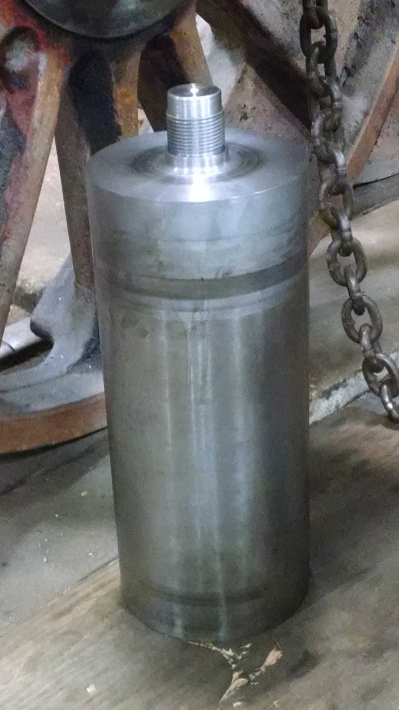
The drivers will each be receiving a new set of tires. Steam locomotive tires are a removable ring of steel, usually weighing several hundred pounds, that surround each wheel center. Just as a tire tread on an automobile wears down from rolling along the highway and is designed to be replaced after a number of miles, the tire on a locomotive also wears down over time due to its contact with the railhead and brake shoes and must be reshaped and eventually replaced. Each of the six driving wheels will be receiving brand new tires during their stay in Strasburg.
Before the new tires are applied, the wheel centers will be turned on a wheel lathe. This process means a thin layer will be shaved off the wheel center (see below photos). By doing so, places of uneven wear or other imperfections will be removed, providing a uniformly smooth and round surface on which the tires can be mounted. As the tires are applied to the wheel centers they are heated which causes them to expand. They are then slid onto the wheel centers and gauged to ensure proper distance between the tires and proper placement on the axle before they cool. When the tires cool and shrink they will grip the wheel centers tightly and, with the freshly prepared surface of the wheel center, will not slip out of place during normal operation.
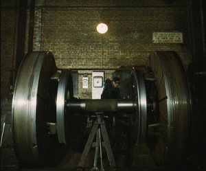
Worn tires are reprofiled on a wheel lathe at the Chicago & North Western 40th Street shops in Chicago in Dec. 1942. C&NW 1385’s drivers will be turned on a wheel lathe similar to this one. Jack Delano photo. Library of Congress collection.
A tire is heated so that it may expand and be fitted to the wheel center. Photo from Atchison, Topeka and Santa Fe shop in Shopton, IA, taken Mar. 1943. Jack Delano photo. Library of Congress collection.
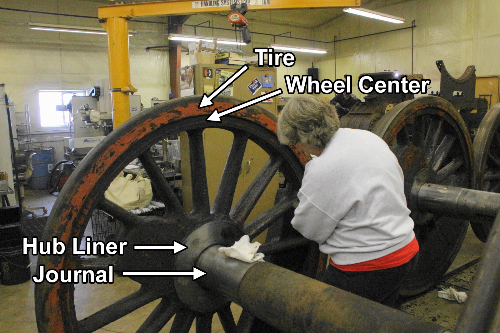
Volunteer Nancy Kaney cleans one of 1385’s drivers. Important parts are identified. See the Jan. 11, 2014 post for more photos from that day. Brian Allen photo.
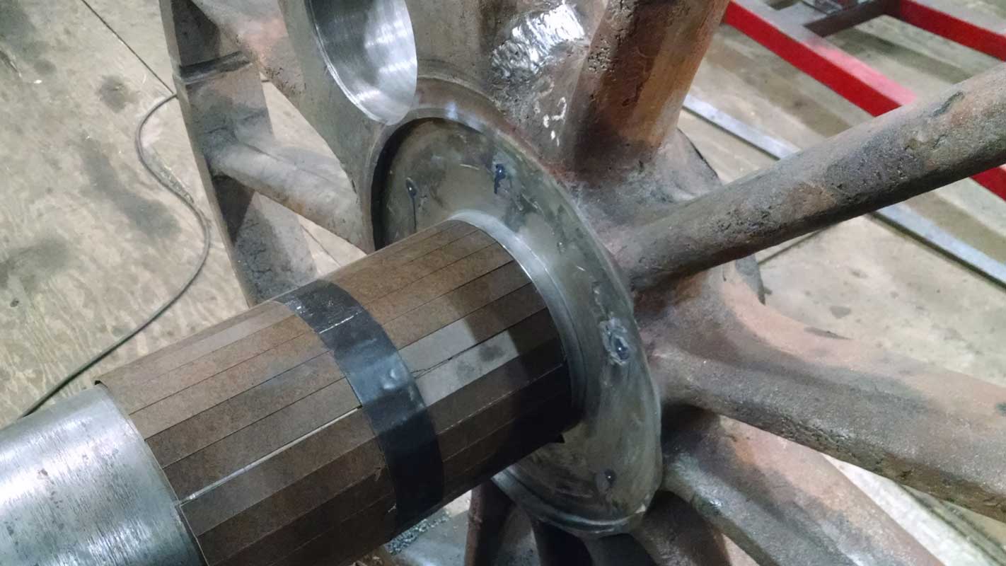
The hub liners, identified on the above photo, will also receive a final inspection at Strasburg.
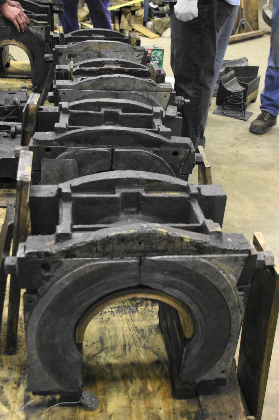
The journal is the portion of the axle onto which the weight of the boiler, cab and everything else supported by the frame, rests. The weight is transferred from the frame to the journals via a driving box. Housed within the driving box is the crown brass, a bronze composition that wraps over the top of the journal. When moving, a thin film of grease prevents excessive friction between the two surfaces, but some friction does still occur. This is the reason the crown brass is composed of softer metal than the journal, to ensure the crown brass receives the majority of the wear. Crown brasses are more easily and cost effectively replaced. Despite these designs, the journal can still be subject to wear over time. The journals of the 1385’s drivers will be carefully inspected and reported on by Strasburg.
In the photograph of the driving boxes the crown brass is the bronze-colored arch seen inside the box. Also shown is the wear plate on the driving box. The wear plate is lined with babbitt which is a relatively soft material (like the brass) and bears on the hub liner of the wheel center during normal operation. The wear plate takes up the side-to-side movement of the axles and provides a relatively easily replaceable component during normal repair.
Steve Roudebush hoists a driving box off a journal. See the Dec. 23, 2013 post for more photos from that day. Brian Allen photo.
The driving box transfers the weight of the boiler, cab, and other components on to the axles. The journal passes through the center. The crown brass is the bronze-colored semi-circular plate lining the inside. The wear plate (on face toward camera) takes on wear from side-to-side movement. Brian Allen photo.
If no surprises are found by the Strasburg shop crew, the refurbishment of 1385’s drivers could be completed as soon as late 2014. When it comes to restoring historic railroad equipment though, not encountering a least a few surprises along the way might be considered… surprising.
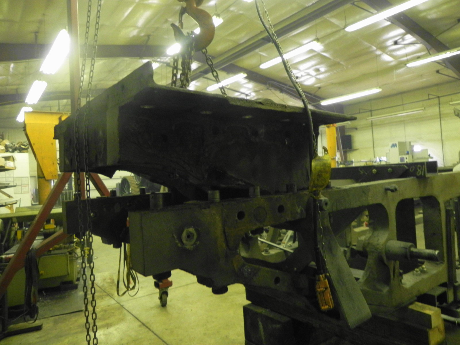
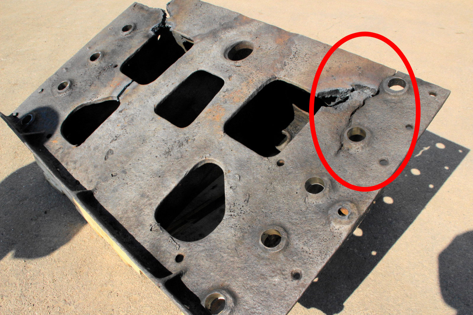
Back at SPEC Machine, work will continue on the frame and additional running gear components. The latest activity has centered on the rear frame plate. On March 24, what the drawings refer to as the footplate was removed. This is a large steel casting at the tail of the locomotive frame that is bolted into the frame. The drawbar that connects the locomotive to the tender – and thereby the rest of the train – attaches to this casting so all the power the locomotive generates is applied to this point. Several cracks and major necessary repairs were found during inspection. The worst crack is highlighted in the photograph below. The cuts in the casting were part of the extraction procedure. For the safety of crew and passengers of future 1385-led trains, as well as to ensure long term operation, it was decided to replace the footplate.
The footplate is hoisted from the frame. Brian Allen photo.
A significant crack (shown in red circle) will necessitate replacement of the footplate. Refer to the Feb. 6, 2014 post to see the inspection in-progress. Brian Allen photo.