Late January marked the return of Chicago & North Western No. 1385’s driving wheels to Wisconsin after nearly 10 months away. All three sets of the locomotive’s 63-inch drivers were sent to Strasburg Rail Road on March 24, 2014 to receive a range of repairs using Strasburg’s specialized machinery and expertise in the field of completing such repairs. Here is a rundown of the repairs which encompassed approximately 350 man-hours of labor.
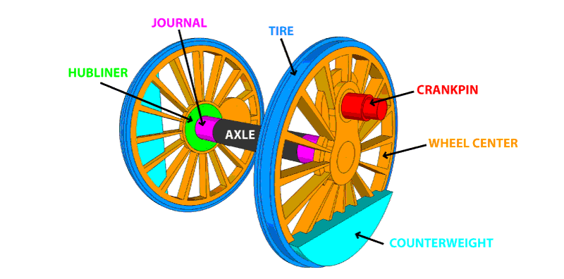
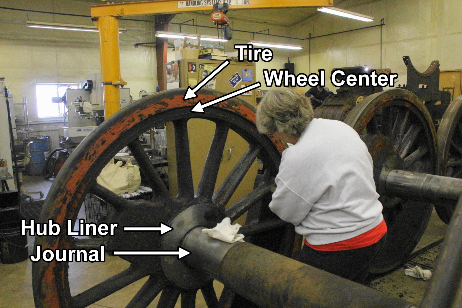
Wheel Centers
Wheel centers are equivalent to the rims of an automobile. It the main bulk of the wheel and includes the central ‘boss,’ spokes and rim.
C&NW 1385 last received wheel work in 1994, four years before its final summer of running in 1998. Mid-Continent’s record of repairs from 1994 show that three of the tires were removed and wheel centers inspected at that time. They were 0.160, 0.127, and 0.124 (inches) out of round. By turning the tire seats on Strasburg’s wheel lathe it returned the wheel centers to perfect roundness and eliminated the need for wheel shims.
The wheel centers were also inspected using magnetic particle inspection, or ‘magnafluxing.’ It is a non-destructive testing process to detect surface and near-surface discontinuities in some metals. A few minor cracks were located in the process. To enact repairs, a steel sample from a wheel was taken and a welding procedure specially tailored to the wheels’ metallurgical properties then devised and completed.
Hubliner
Hubliners are metal disks that are mounted on the inward-facing side of the wheel centers and are designed to absorb the wear where contact occurs between the wheel and the driving boxes. While at Strasburg, one of the six hubliners was replaced while the remaining five were all refaced to provide a smooth, even surface.
Journals
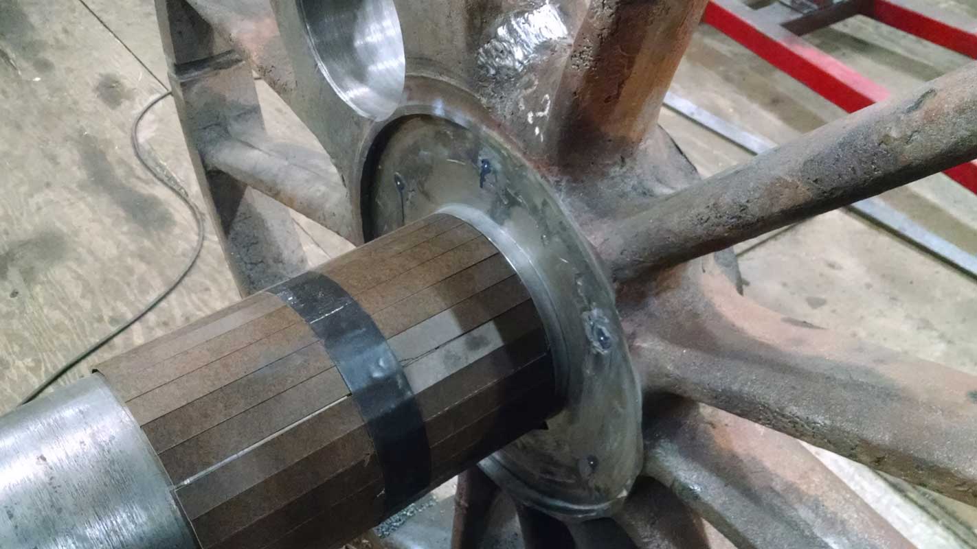
Journals are the portion of the axle, just inside the wheels, where the weight of the locomotive rests.
No. 1385’s journals were found to have scratches and other minor issues. Polishing was attempted but the imperfections were found to be too deep. To bring the engine to mainline-ready condition, the journals were turned and then polished to produce a smooth surface.
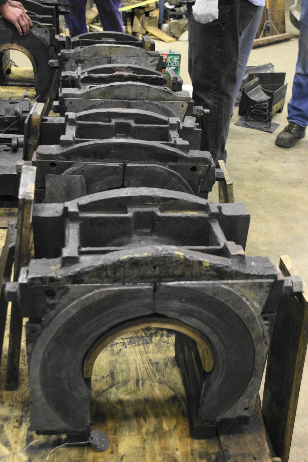
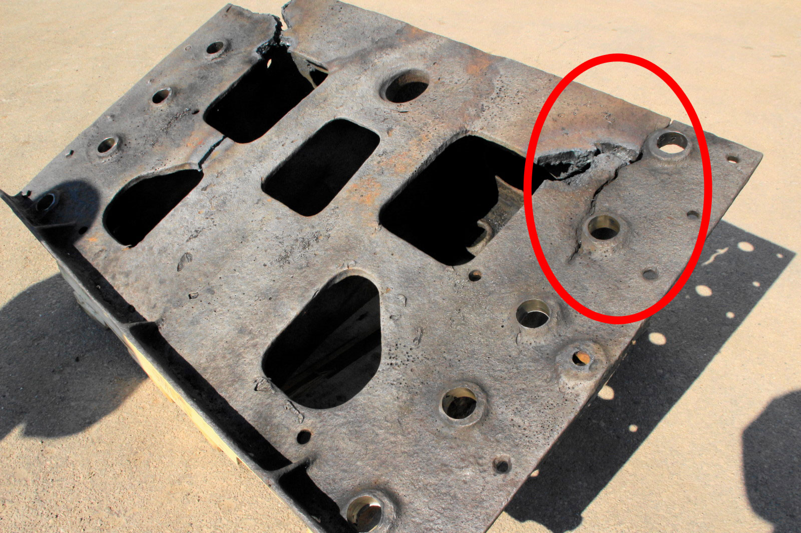
By making adjustments to the journal, it was also was necessary to make corresponding adjustments to the journal boxes. The journal box is what transfers the weight of the locomotive from the frame to the axle. Inside the box is a crown brass, shaped to fit over the top of the axle. The crown brass must be a perfect fit so as to allow just a film of journal oil to form between the journal and the crown brass and thus prevent overheating from friction.
With the final dimensions of the journals now known, the driving boxes were sent to a local shop in Baraboo, Wis. to machine the crown brasses. Inspection revealed one of the six brasses worn beyond accepted limits and that brass has been replaced. The other five proved to have sufficient material left to provide a long service life.
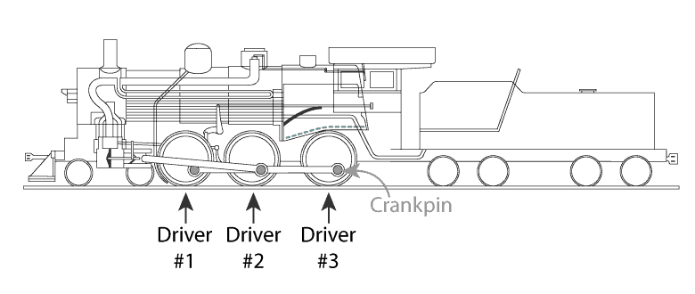
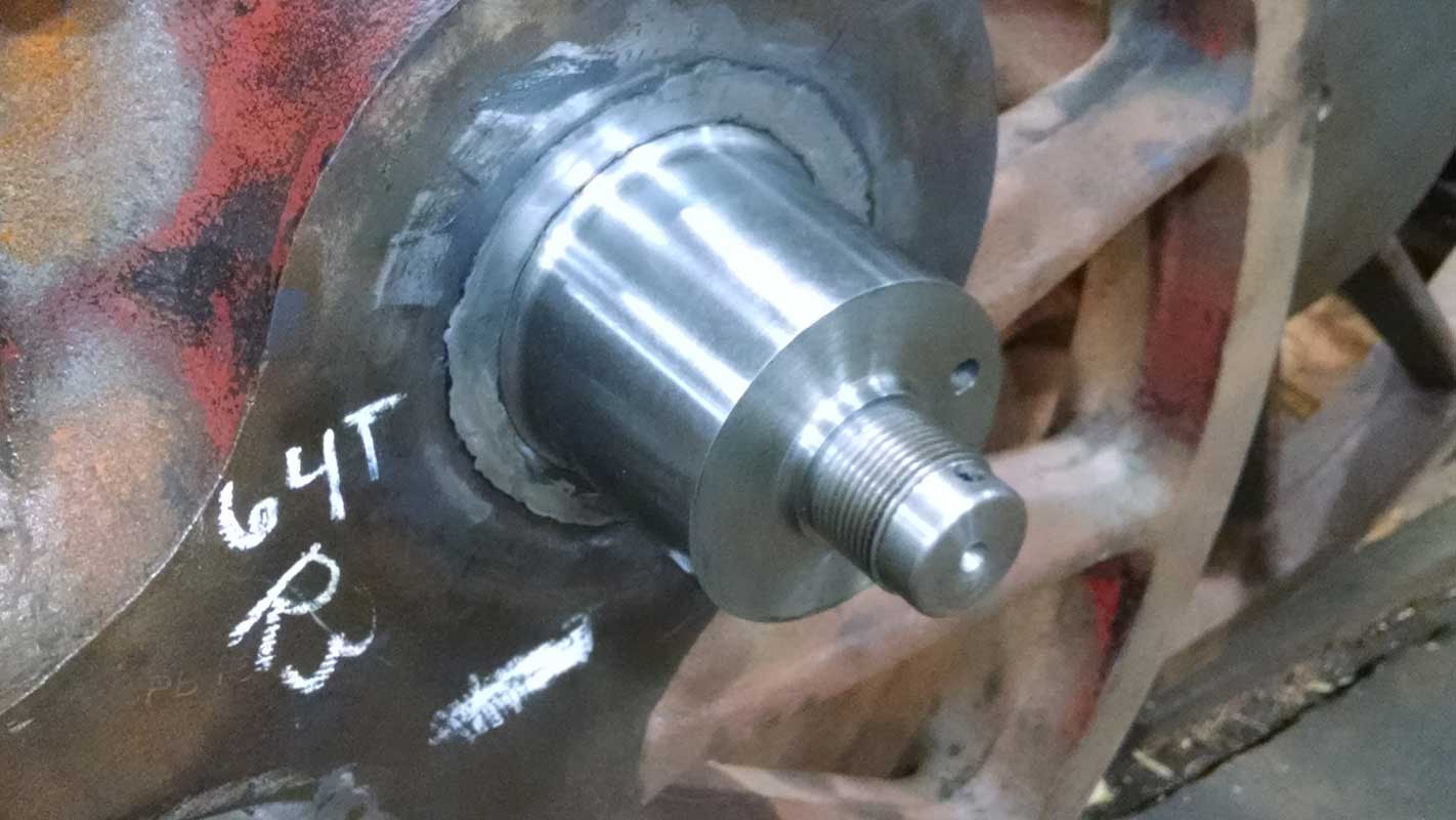
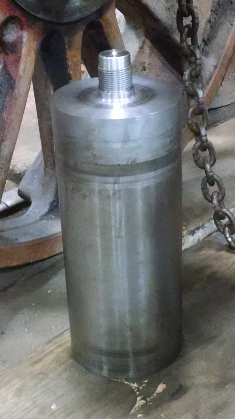
Replace Crankpins
Crankpins transfer forces between the rods and wheels. The forward and rear drivers have smaller crankpins because they only connect to the center (main) driver via side rods. The main driver has a larger crankpin because it connects to both side rods and the main rod. To offset the weight of the larger crankpins and rods, the main driver requires a heavier counterweight.
 The main crankpins and the crankpins on the rearmost driver were found to be worn beyond American Locomotive Company’s standards and were replaced. The crankpins on the first driver were in good enough condition to allow for machining in order to renew the bearing surface.
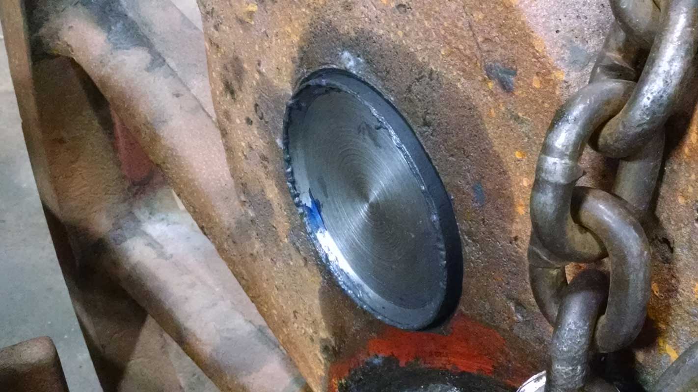
Quartering the Crankpin Holes
In order to work properly, a driving wheel must be offset (rotated) by exactly 90-degrees from the wheel it is connected to via the axle on the opposite rail. As 90-degrees is one-quarter turn of a wheel, the process is called ‘quartering.’ The holes to receive the new crankpins were bored and then the crankpins themselves were machined in such a way as to maintain exact quartering.
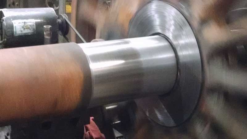
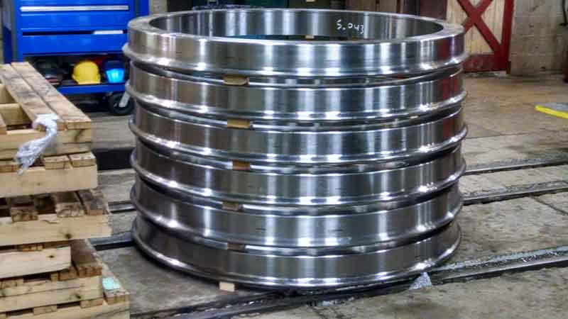
Installing New Tires
Similar to how tires on a car are designed as readily replaceable items designed to absorb the wear of going down the road, a tire on a locomotive fits over the wheel center and is designed to absorb the wear of rolling down the railhead and use of the locomotive’s brakes.
Project volunteer, Ed Ripp, adds some detail:
“The tires that were on the wheels were the tires that were originally on the engine when it came to Mid Continent [in 1961]. The running gear work that was performed in [1994] included just re-profiling the tires, not replacement. With just 1,000 miles or so of running since then, some significant flange wear on one tire developed that was near FRA wheel profile condemning limits. In order to bring that one tire into compliance, all of the other tires have to be turned to the same diameter. This is due to the fact that the drivers are coupled together with the side rods.”
As a result, No. 1385 received new tires for all six wheels so they could all be equal in size with a lot of life to avoid the need for another round of maintenance in the near term. Several hardness levels are available from which to choose when having tire made, based upon expected usage and environmental factors. No. 1385 received Grade C hardness tires.
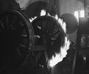
In order to prevent the tires from coming off in operation, they are custom ordered to fit down to within thousandths of an inch. They are sized approximately 1/16 inch smaller than the wheel center onto which it must fit. They are then heated to cause expansion, enabling them to slide into place. Once cooled, the fit becomes tight. Strasburg Rail Road took a video of the process and it is available for viewing on their YouTube page.
[youtube]9L3oaA-nxzY[/youtube]
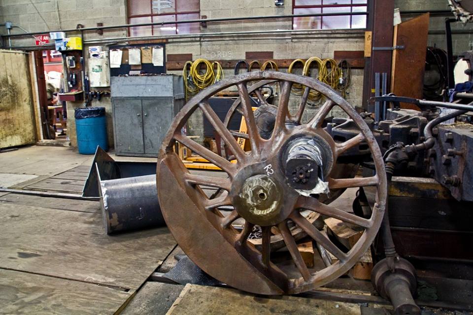
Return to Wisconsin and Painting
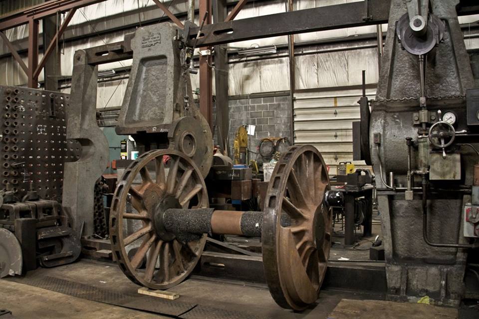
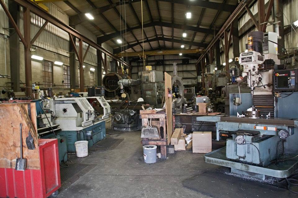
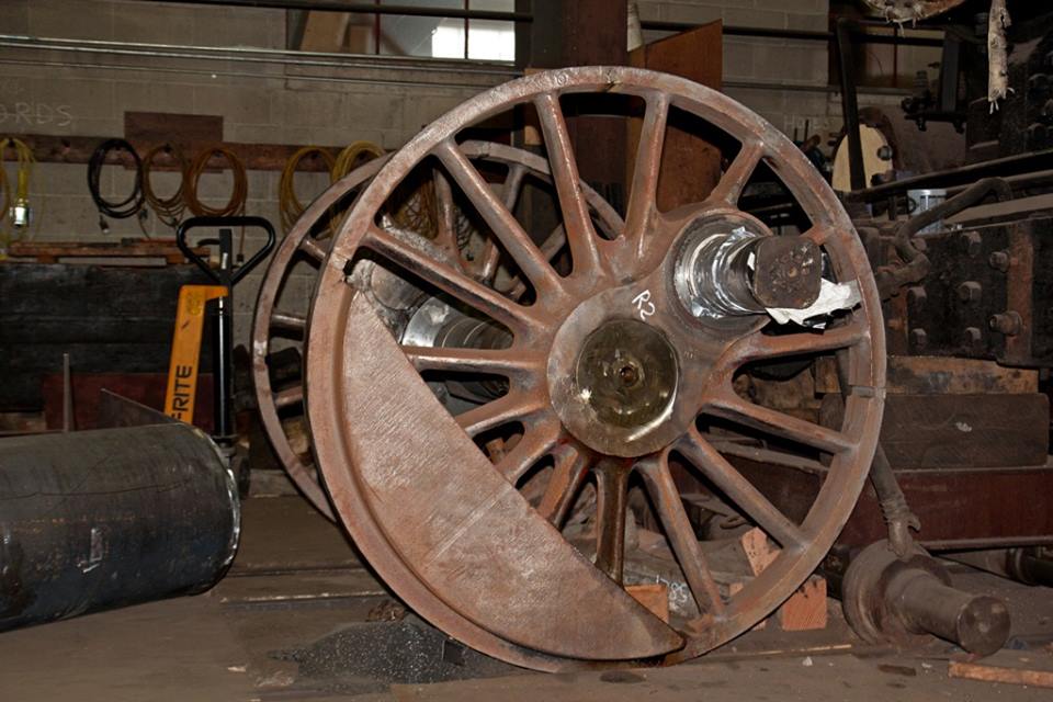
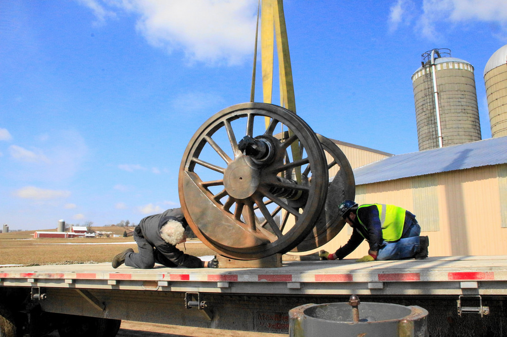
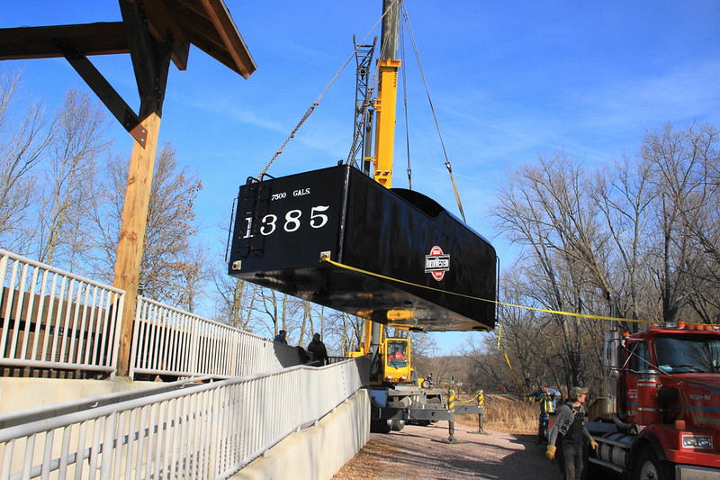
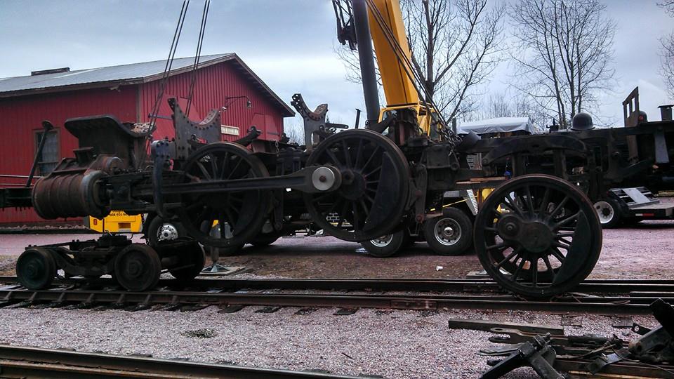
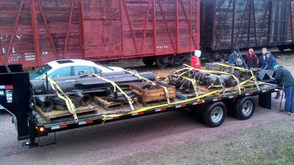
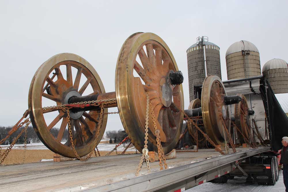
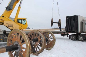
Following completion of repairs at Strasburg Rail Road, the drivers were trucked to SPEC Machine where they arrived on January 22, 2015.
-
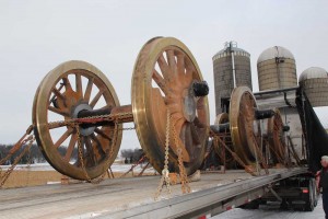
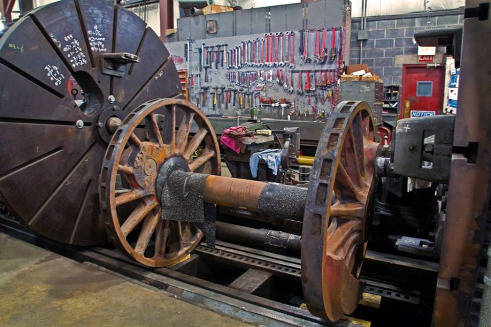
- C&NW 1385 refurbished driving wheels being unloaded at SPEC Machine. Jan. 22, 2015.
-
- C&NW 1385 refurbished driving wheels being unloaded at SPEC Machine. Jan. 22, 2015.

More images of the arrival of the driving wheel are available on photographer Brian Allen’s Flickr page.
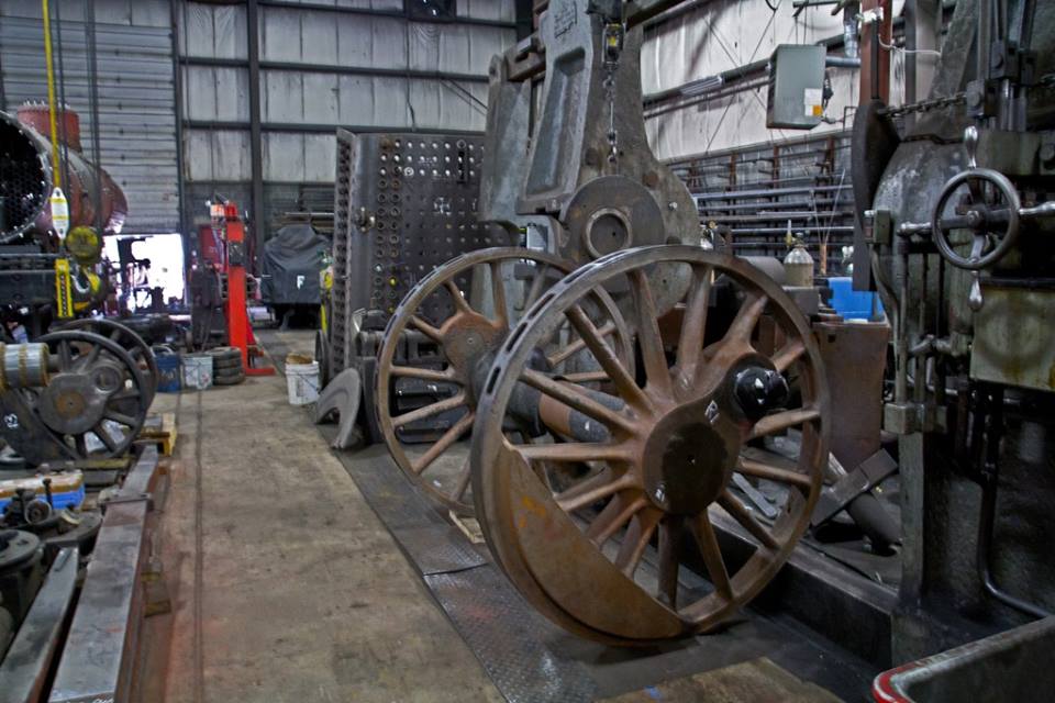
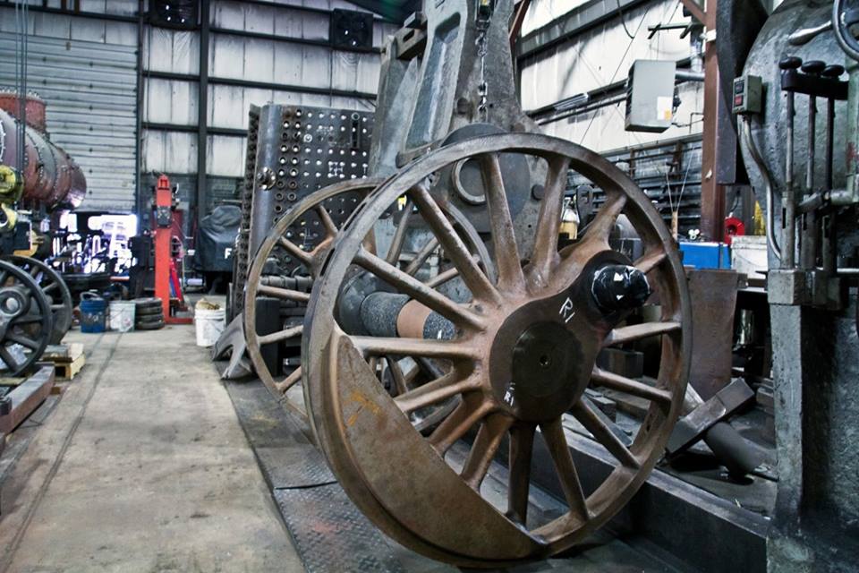
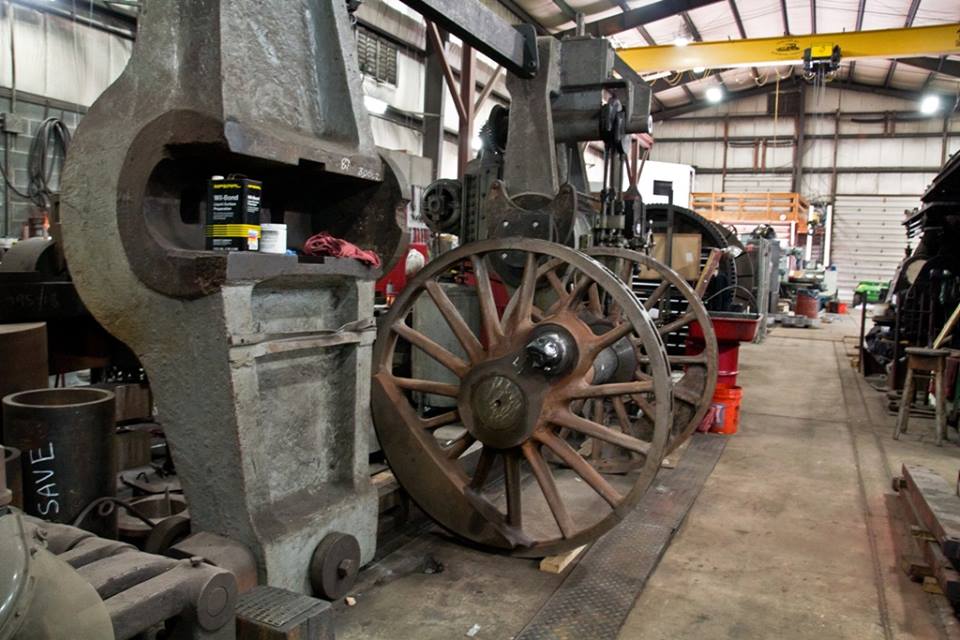
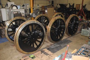
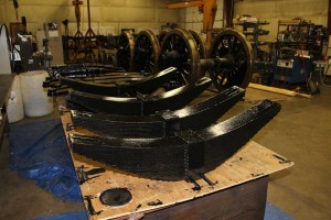
Within a few days, the wheel centers along with various spring rigging components were painted black.
-
- C&NW 1385 spring rigging after painting. January 2015. Brian Allen photo.

-
- C&NW 1385 driving wheels with painted wheel centers as of late January 2015. Brian Allen photo.

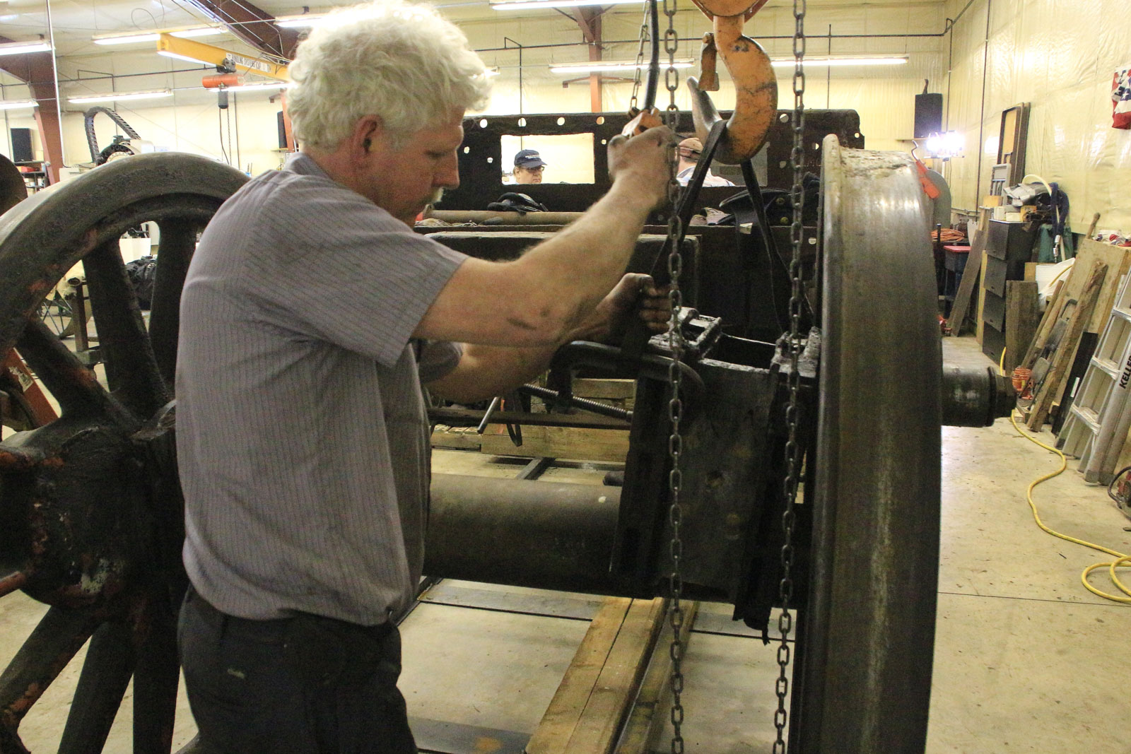
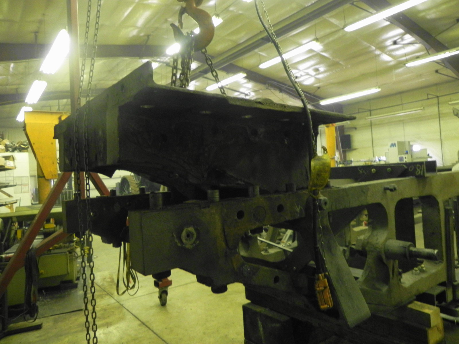
Meanwhile, progress has been made on the driving boxes and the beginning of reassembly of the running gear, but that will have to wait until another post.