Join the Mid-Continent Railway Operating Crew
Here is a unique opportunity to be a part of our working railroad by joining the Mid-Continent Railway Museum Operating Department. We are now accepting applications for our training school beginning which starts on April 13, 2019.
What does a trainman do?
Note: The term ‘trainman’ is the historical job title used by railroads of the era and thus is used at Mid-Continent. Women can and do serve as trainmen as well and are encouraged to participate in all facets of museum operations.
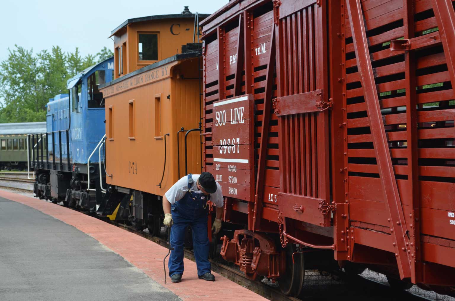
Trainman inspecting journal boxes.
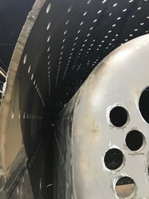
Trainmen work alongside the conductor, fireman, and engineer to operate demonstration train rides for museum visitors. The position includes physical aspects: coupling/uncoupling cars, guiding train movements, inspecting cars, etc. It also includes social aspects: speaking with museum visitors and passengers, answering questions, and serving as a public face of the museum.
What is taught in the class?
During your four day training (two weekends) you’ll learn the basic operating and safety rules in use by Mid-Continent Railway during classroom sessions and then working outside with the museum’s equipment during the hands-on portion.
Eligibility requirements
Only Mid-Continent Railway Museum members ages 18 and above and in good standing are eligible. (Learn about becoming a member). Four days of in-classroom and on-site training is required followed by individually scheduled days of job shadowing and a final qualifying test. Persons qualified on other railroads are not exempted from the required training. Limited class space is available and signup is offered on a first-come, first-serve basis.
Keep in mind that some aspects will require you to be physically capable of – but not limited to – performing such tasks as throwing switches, replacing coupler knuckles, minor rolling stock maintenance, climbing onto and off of equipment, and working in all types of weather conditions.
Do I have to know a great deal about trains and railroad history to enroll?
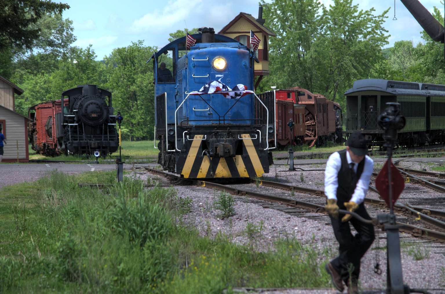
A trainman throws a switch for MCRY #7.
What you need to know about train operations will be taught to you in class. As for general railroad and railroad history knowledge, there are no prerequisites or tests. You will learn a lot just by going through the class and student trips and being around fellow volunteers. Your instructors may have suggested reading materials for you as well.
How frequently is the class offered?
The trainman class is offered once per year, each spring.
Is there a class to become a conductor or locomotive engineer?
Yes, but all new train crew volunteers are required to first start as a trainman.
How much does the class cost?
The cost to attend is free, but you will need to equip yourself with the proper clothing and purchase a rule book which will be explained in the trainee’s invitation email.
What is the time commitment?
The training program last four days (April 13-14 and May 4-5, 8 AM-5 PM each day). This must be followed up by completing three-to-four of student trips prior to the end of the operating season. Student trips are done on your schedule and can be completed during most any day that trains are operating.
In subsequent years, volunteers are expected to volunteer in train crew service a minimum of four days each year to remain qualified. Every third year train crew members must also attend a one-day refresher and recertification test.
What if I am not a Mid-Continent Railway Museum member?
Museum membership is open to anyone and starts at $40.00 per year. For more information on membership, see the Join Us page.
How do I sign up for the class or find out more information?
Simply contact the Mid-Continent Railway Museum office at 608-522-4261 or inquiries@midcontinent.org to verify your museum membership status (or sign up to be a new member) and then be put in contact with MCRM’s Operating Department training officer.
