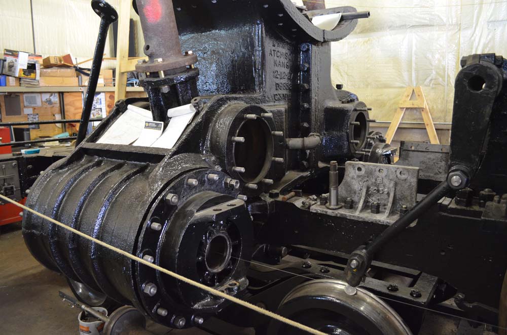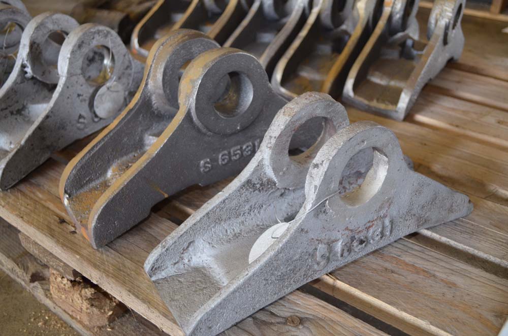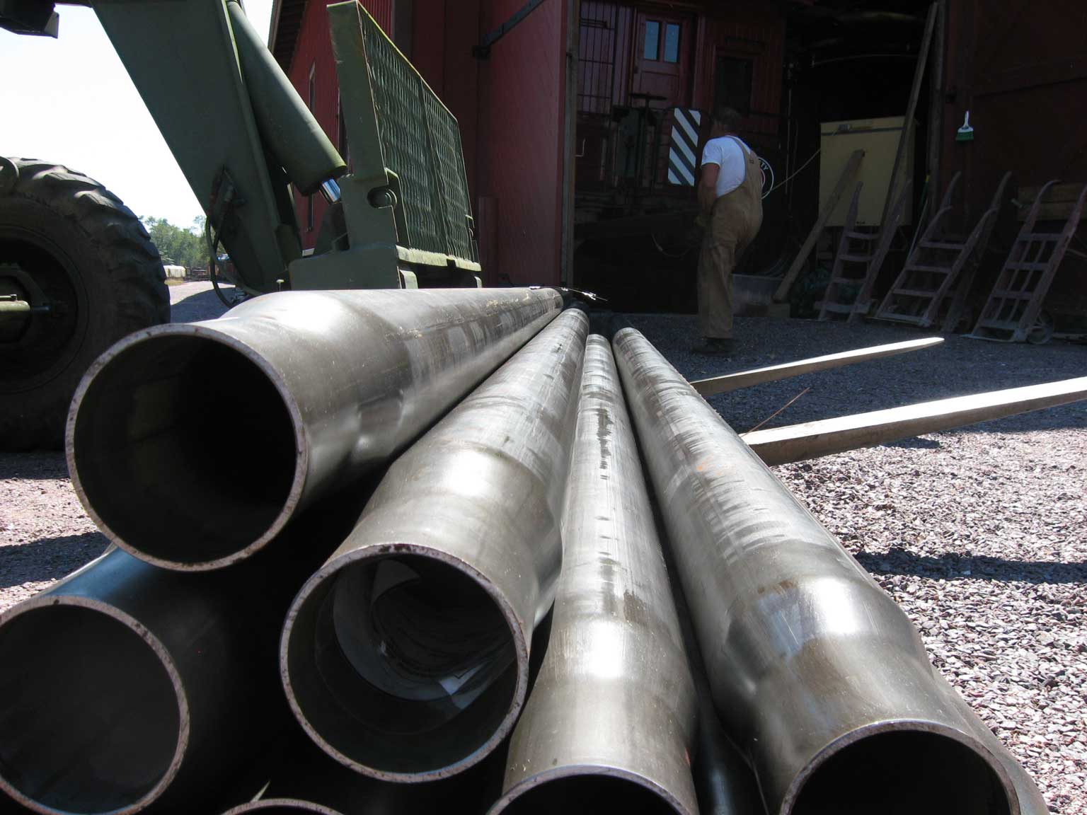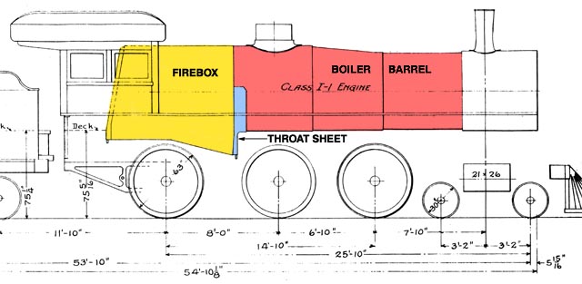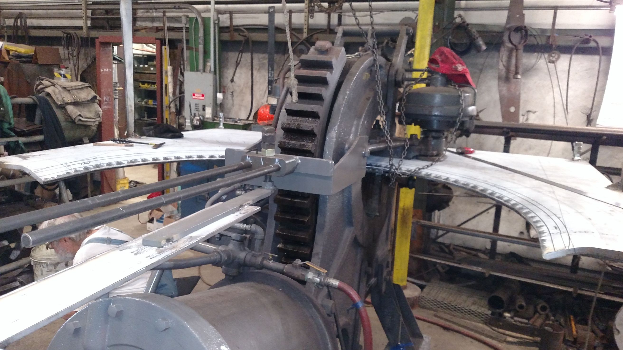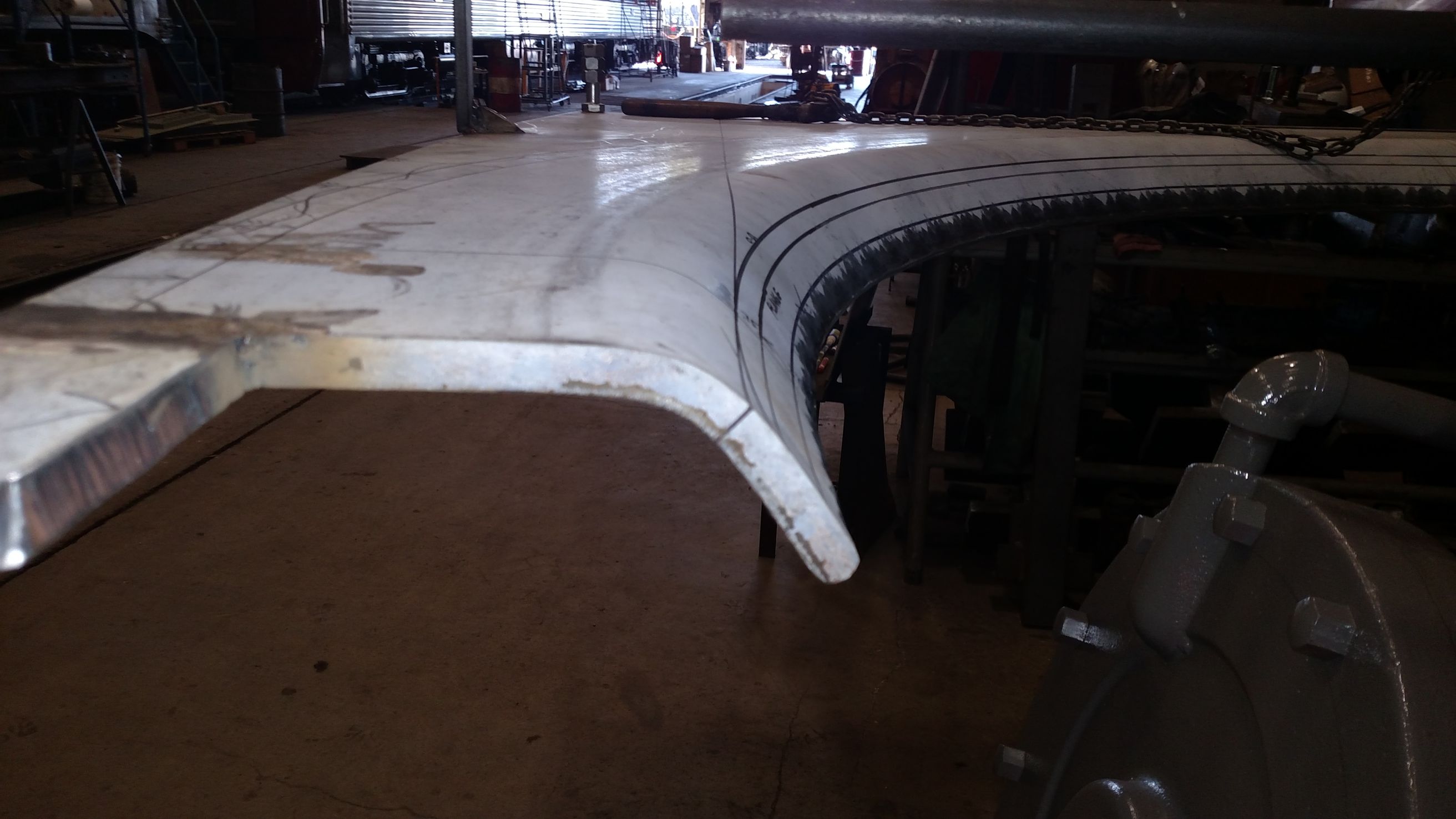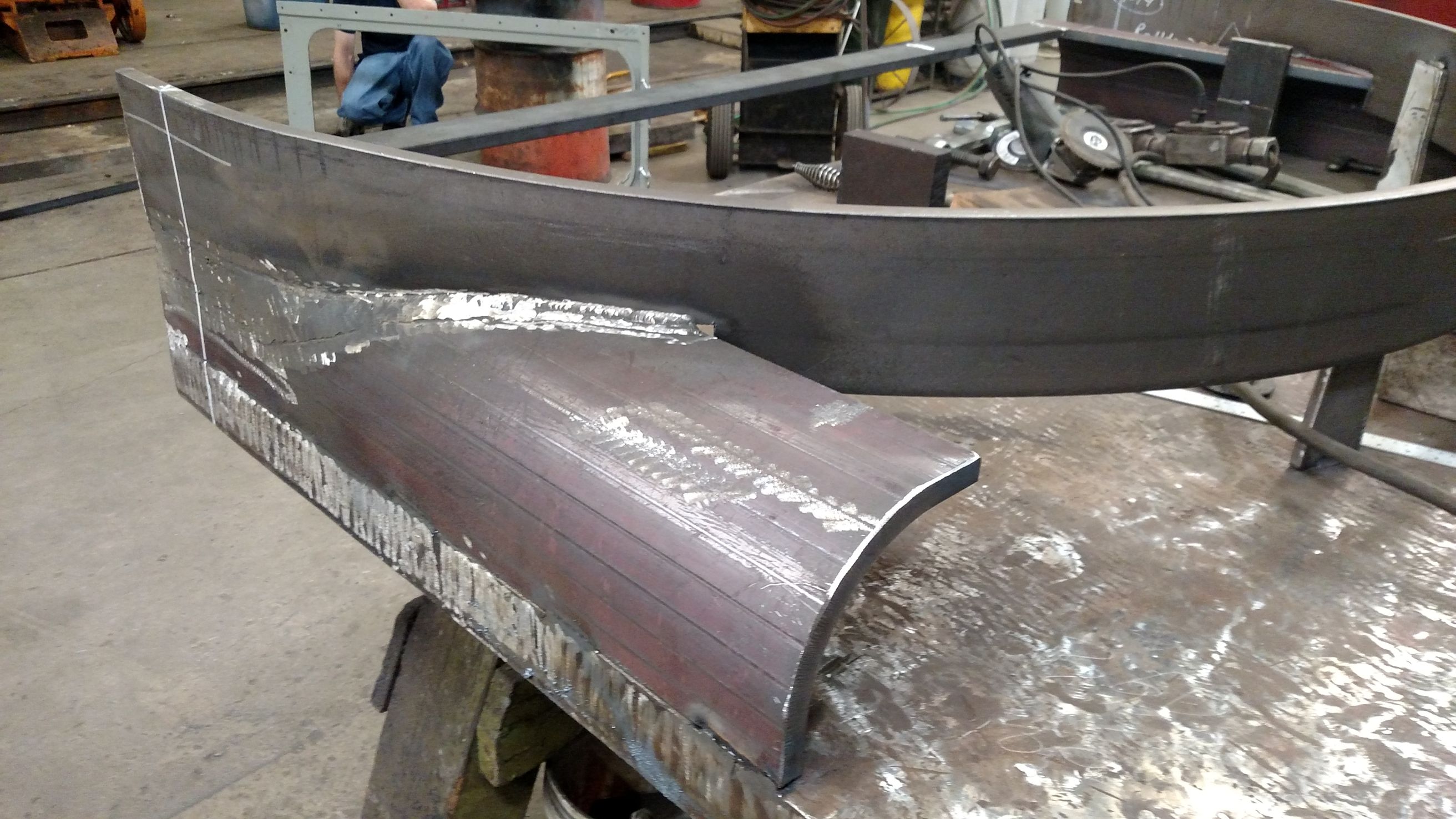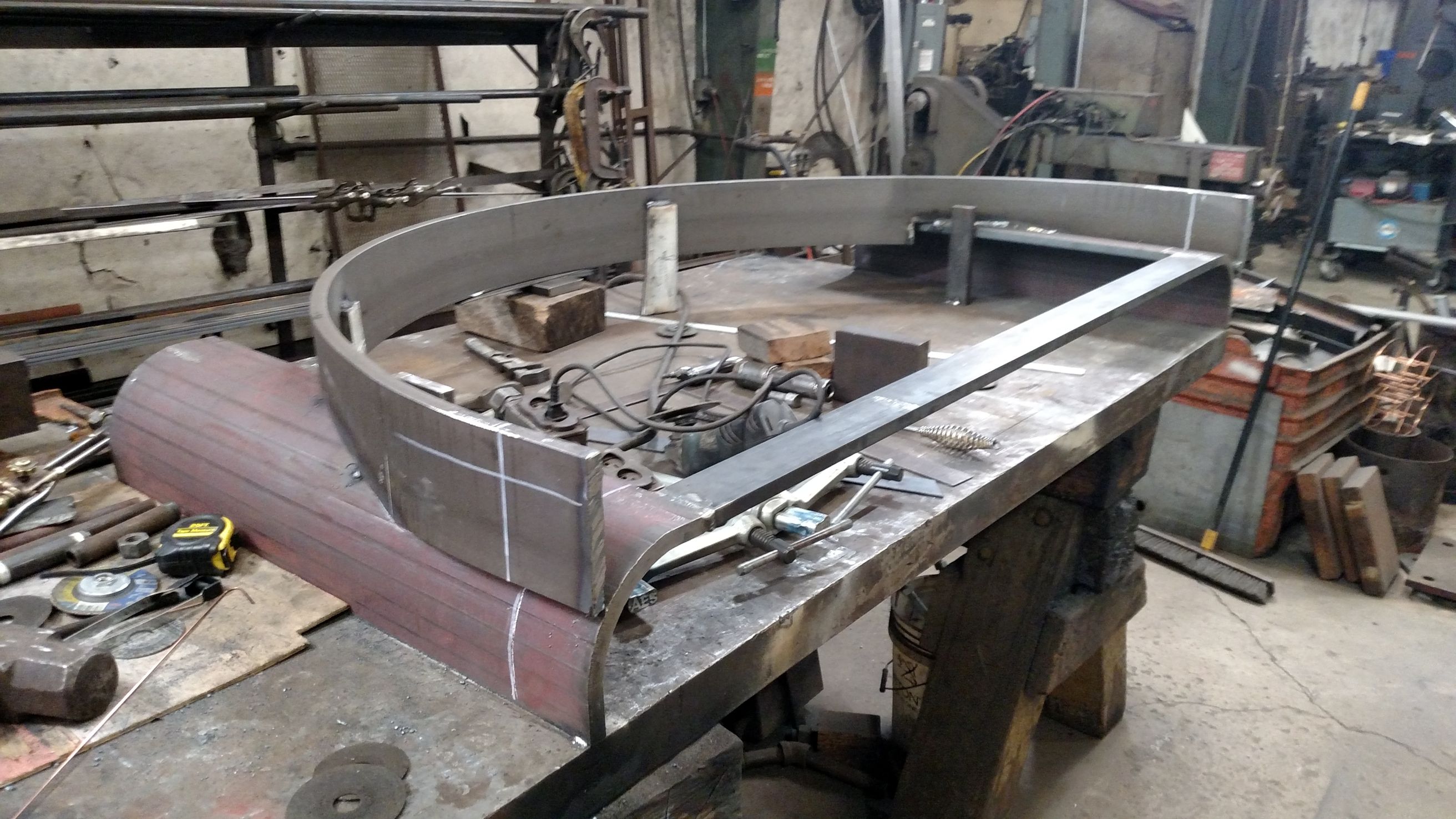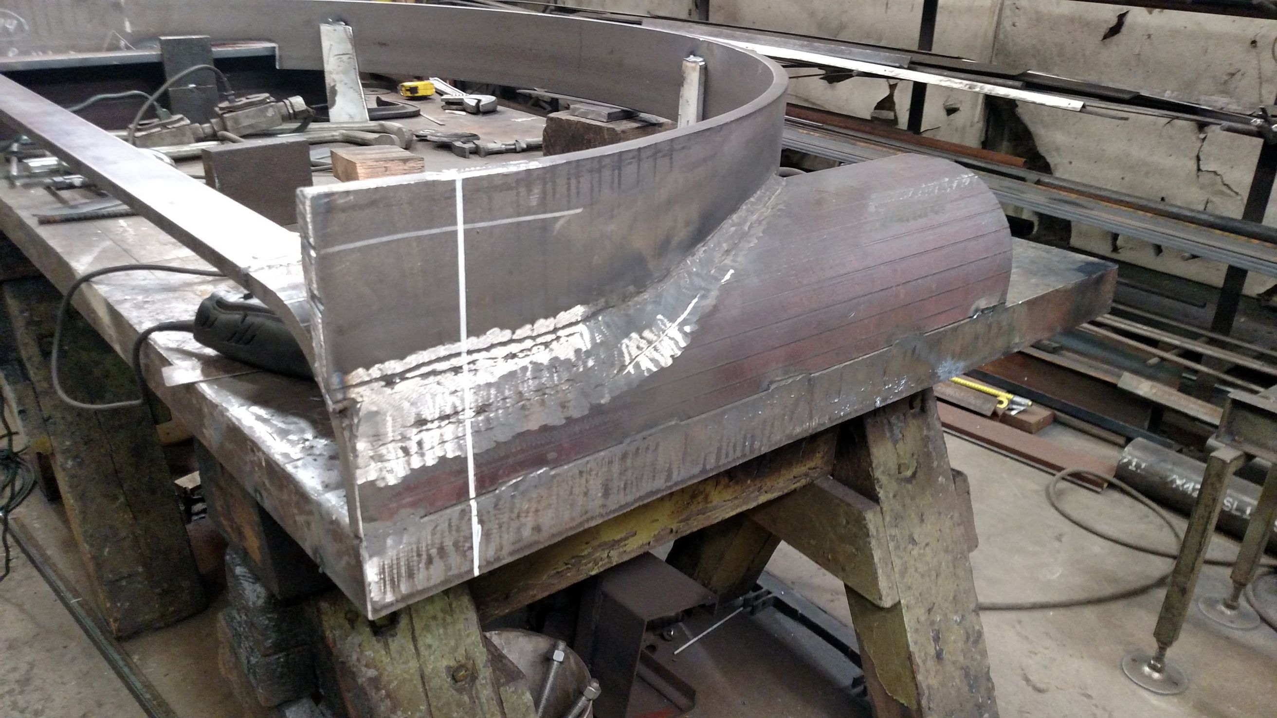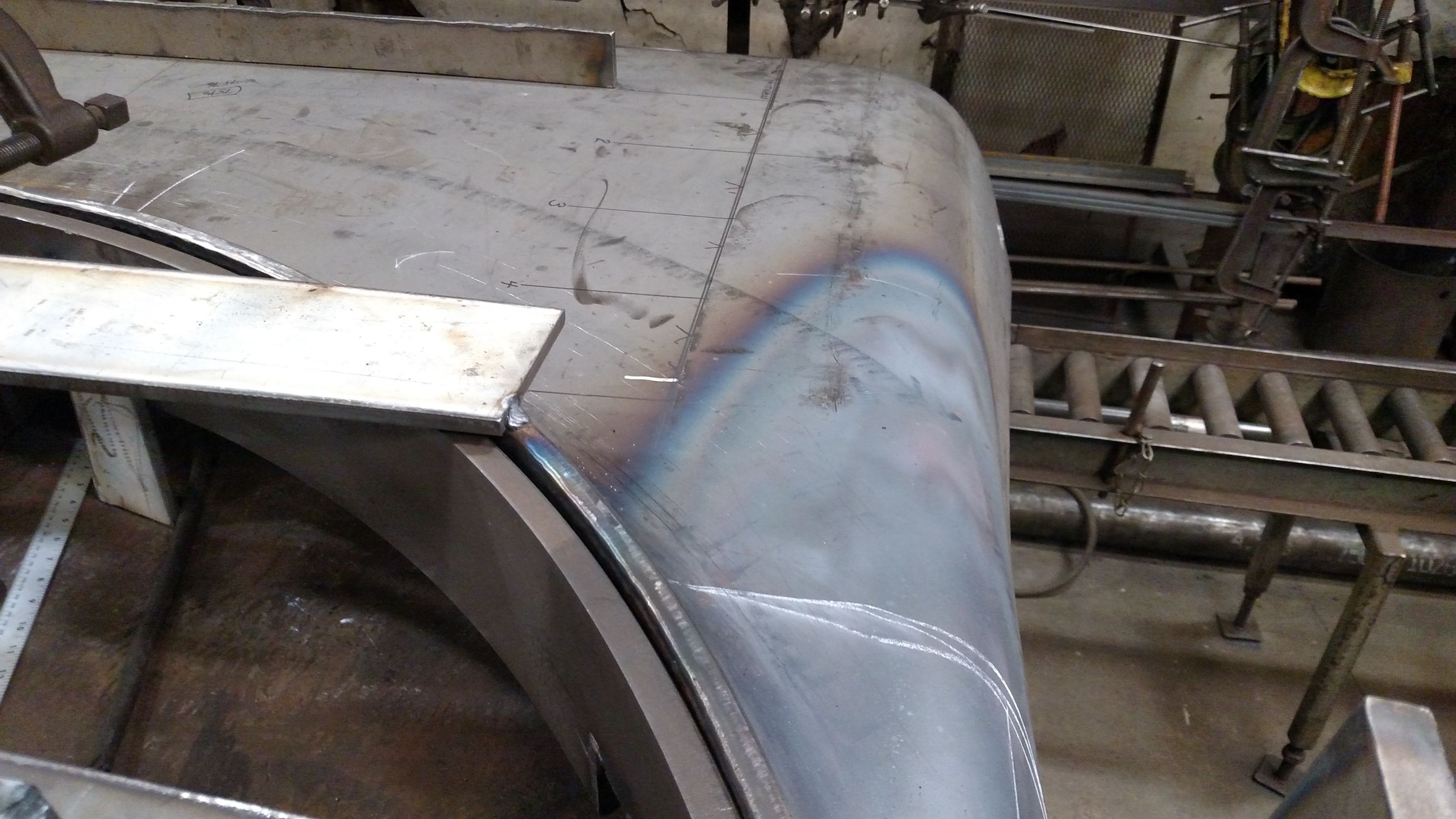
Specs and drawings are finished for the boiler and all current drawings have been released to Continental Fabricators in St. Louis, the manufacturer of Chicago & North Western #1385’s new boiler. Continental spent late November and December working on the firebox. The stay bolt layout is in full swing with cutting and fitting the sheets taking place in December.
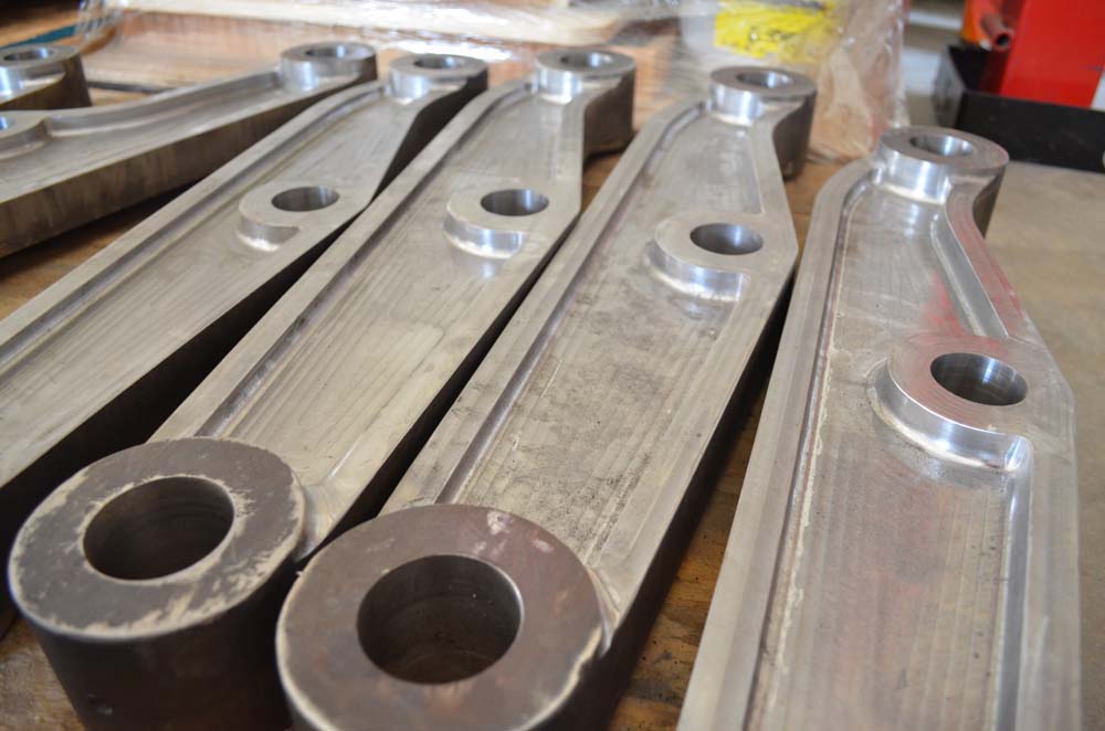
Stay bolt sleeves and washout components are currently in process at SPEC Machine. Stay bolt lengths have been compiled so that work can begin on machining these components in preparation of the firebox assembly.
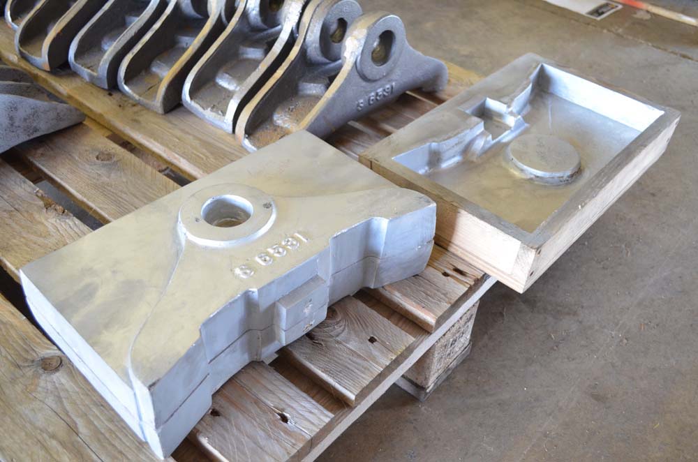
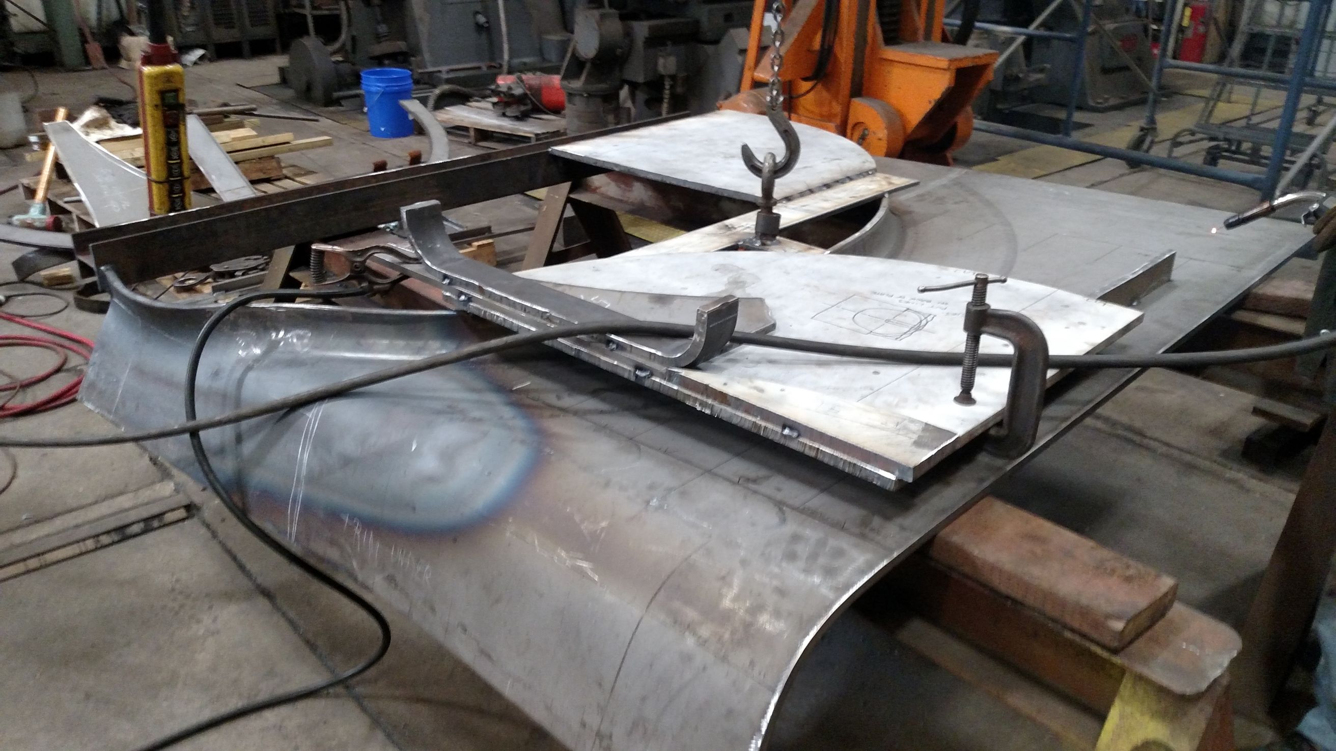
There will be an amount of trial and error with the sizing and tolerancing of some of the components. The welding process that each will endure during fitting to the boiler has the potential to distort the parts significantly. SPEC Machine is building some sample parts to try to simulate the installation process. These samples will better estimate how much distortion to expect so the appropriate adjustments can be made. This will require some extra work but will minimize the potential for these parts to cause issue on on the actual boiler.
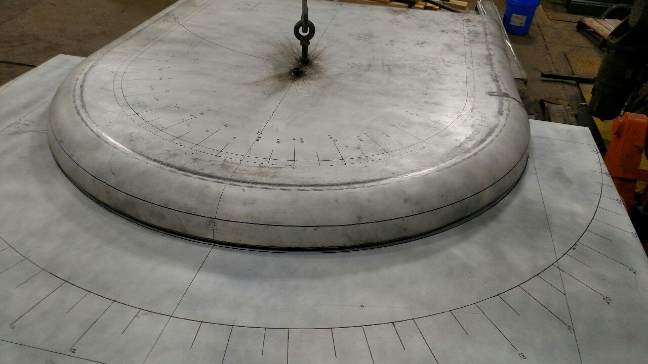
The latest engineering work has been centered on the the steam dome. Designs are currently being reviewed by Continental Fabricators with an emphasis on compliance with American Society of Mechanical Engineers (ASME) code.
Continental Fabricators is currently set to begin production of the bulk of the boiler in early-to-mid January. Once production ramps up, things should move quickly with the new boiler anticipated to be completed in late March or April 2018.
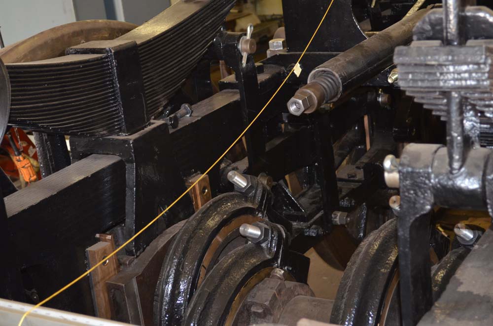
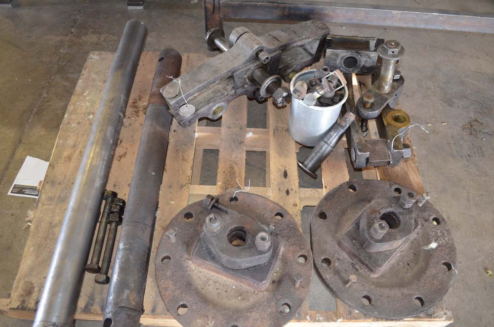
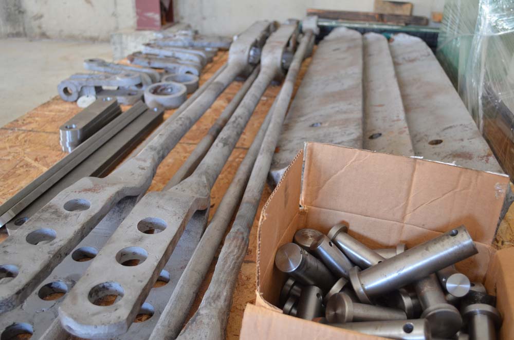
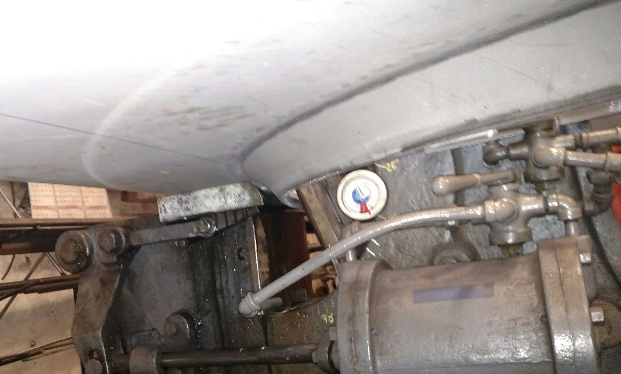
Upon completion of the boiler, it will be shipped to SPEC Machine in Middleton, Wis. where it will be set onto the running gear. In the intervening three to four months, the 1385 Task Force and SPEC Machine personnel are doing their best to have the balance of the locomotive ready. The goal is to for the most part complete the repair phase on the rest of the locomotive so by the time the boiler arrives, efforts can be entirely focused on reassembly. The plan calls for having as many parts as possible finished being machined or cast so workers can simply grab an item from the shelf, attach it to the locomotive and move on to the next item. Areas that are going to be seeing attention in the coming weeks include items like grates, grate bearers, brackets, water glasses, throttle linkages, lubricators, journal pads, oil celler liners, and many other small but crucial parts.
Part of preparing the locomotive for the boiler’s arrival involved moving it into SPEC Machine’s new shop bay. The preexisting shop did not have adequate clearance for the 1385 in a fully assembled state so an expansion of the shop was required with a larger door and higher ceiling clearance. That construction project was completed in late fall 2017.
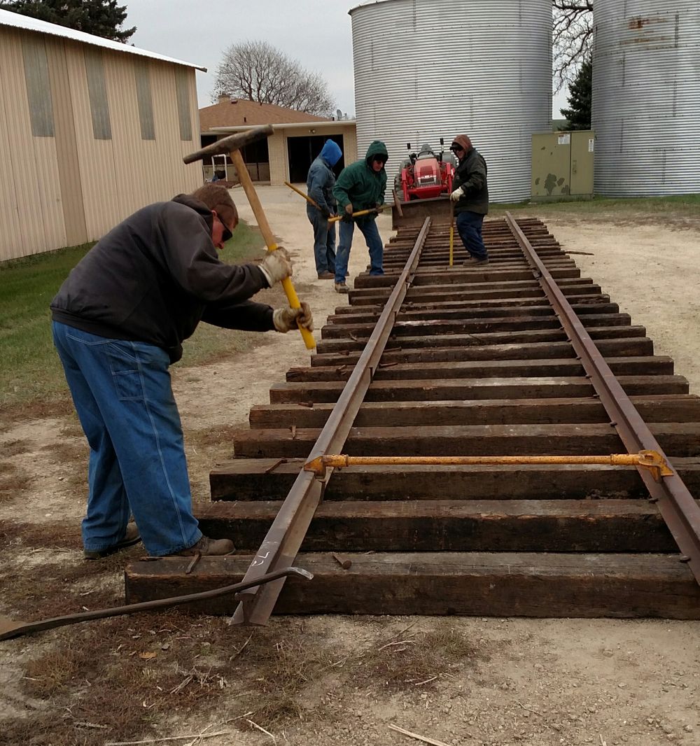
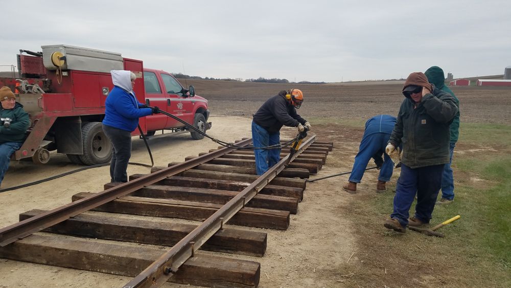
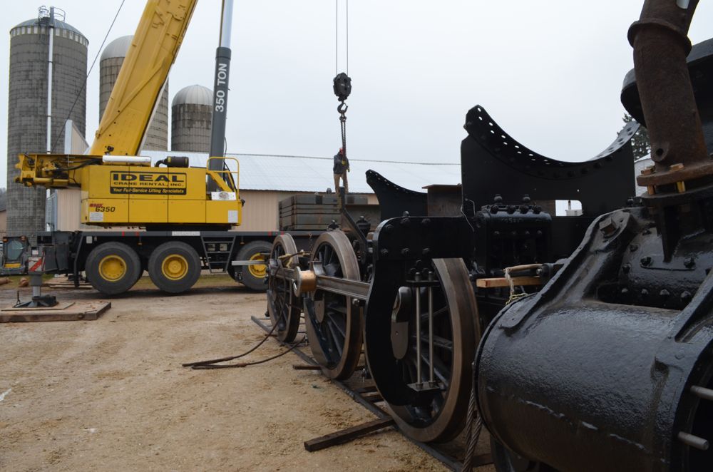
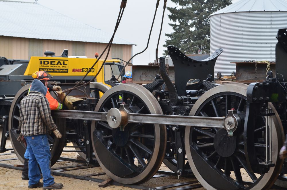
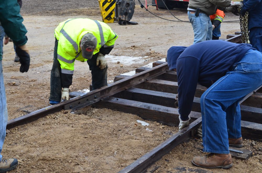
With the new shop bay ready, the next step was to move the 1385’s running gear to its new berth. What sounds like a relatively small task was anything but. Even without the tender, boiler, or cab to worry about, the locomotive’s running gear alone still weighs approximately 90,000 lbs. The first task was to construct temporary panel track into the new shop bay. Volunteers gathered at SPEC Machine on November 11th to construct 60 feet of new track.
MCRM volunteers Ed Ripp and Dick Gruber, both of whom’s careers are in the Wisconsin & Southern Railroad’s maintenance-of-way department, led the effort. The other volunteers, all of whom were new to track work, were ready and eager to be imparted with knowledge. Lessons included using the proper tools for the job and how to work smarter, not harder. Each person got a chance to try all the various tasks. Nancy Kaney, one of the first-time gandy dancers commented, “It was a great learning experience. Dick and Ed were really good teachers.”
-

- 11/11/2017. Laying track at SPEC Machine. Nancy Kaney photo.
-

- 11/11/2017. Laying track at SPEC Machine. Richard Colby photo.
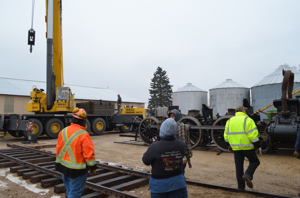
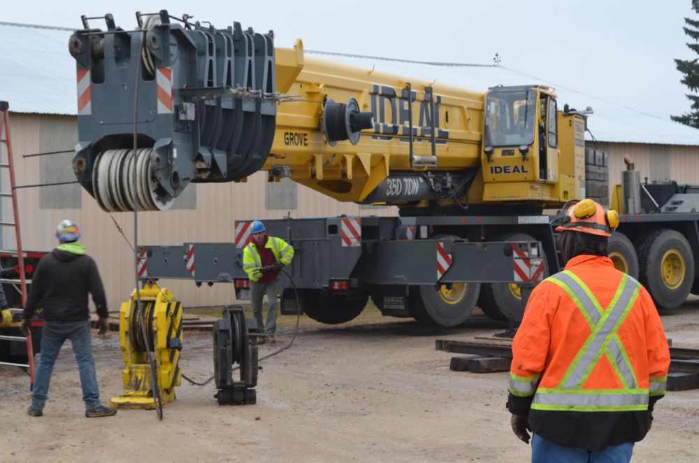
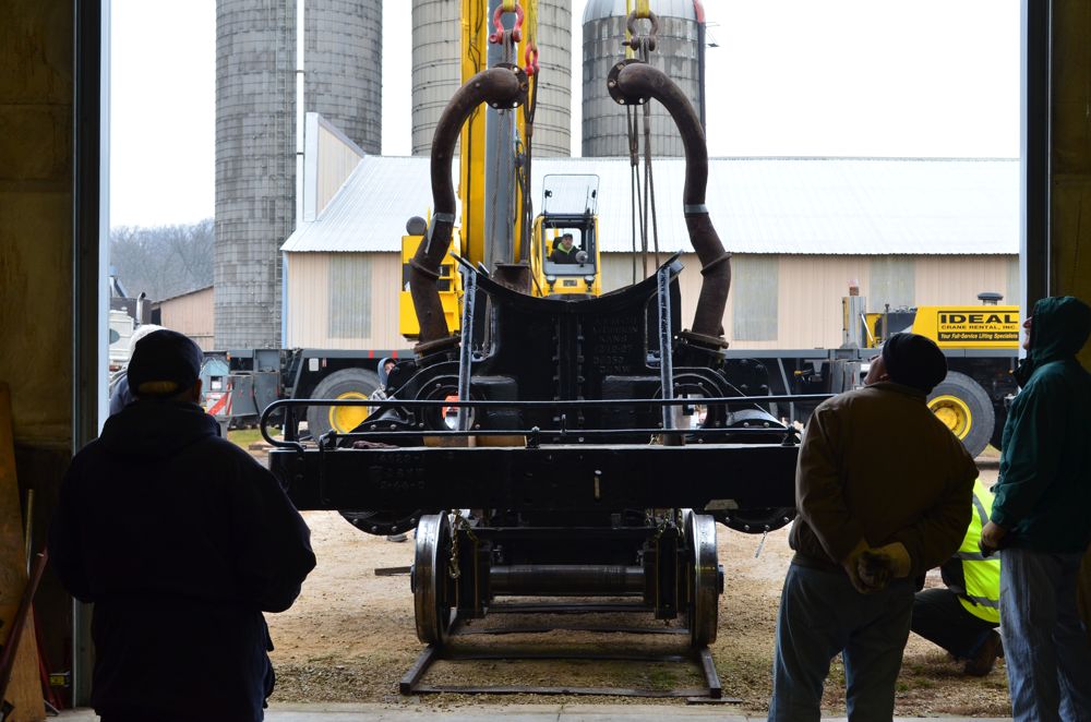
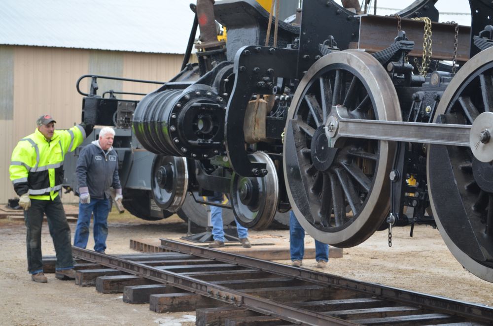
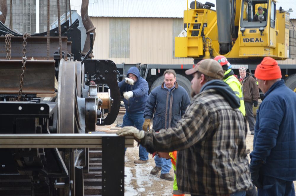
With the panel track prepared, the next step was to move the partially reconstructed locomotive into the new shop bay, a distance of only about 30 feet. This took place December 18th. Volunteers began arriving around 5 a.m. to lubricate and tow the locomotive out the shop door. A crew from Ideal Crane Rental arrived at 7 a.m. and began setting up the crane and adding the necessary 100,000 lbs. of counterweights.
-

- Crews add counterweights to the crane in preparation of the lift.
-
- Lifting cables are attached and ready.
MCRM volunteer Ed Ripp looks on as the crew from Ideal Cranes readies for the lift.
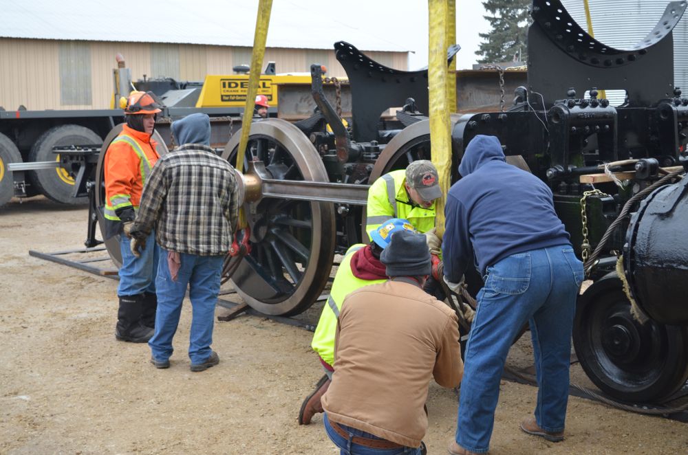
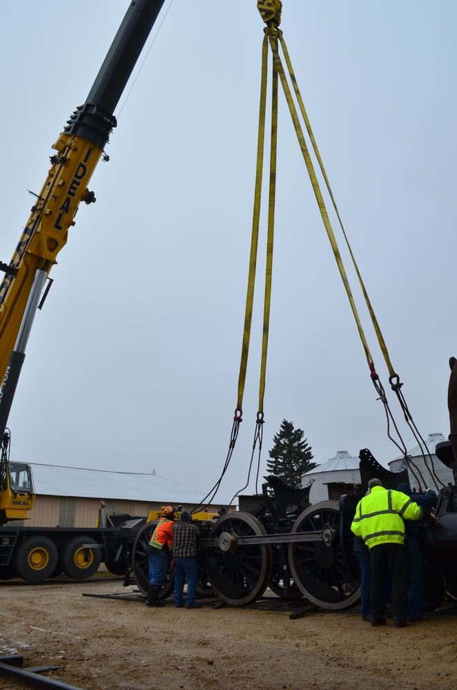
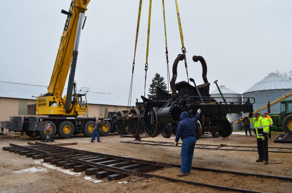
By 9 a.m. a small crowd of 20 or so volunteers, family, friends, and well-wishers had gathered to watch the process. The first lift attempt occurred shortly after 9:30 a.m. but was was halted so that a few small brake components could be removed to avoid taking damage from the lifting cables. A few minutes later they were ready to try again but had to stop when the the fireman side of the locomotive was raising slightly faster than the engineer’s side. After a few minutes of adjusting the cable lengths, the crane operator tried once more, this time gracefully hoisting the roughly 90,000 lbs. and four years worth of hard work off the ground.
-
- Attaching the 1385 to the crane.
-

- Double-checking the attachments prior to lift.
-
- Once last check before picking up the 90,000 lbs of running gear.
-
- Volunteers look on as the crane begins to lift.
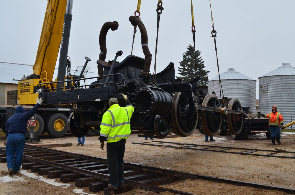
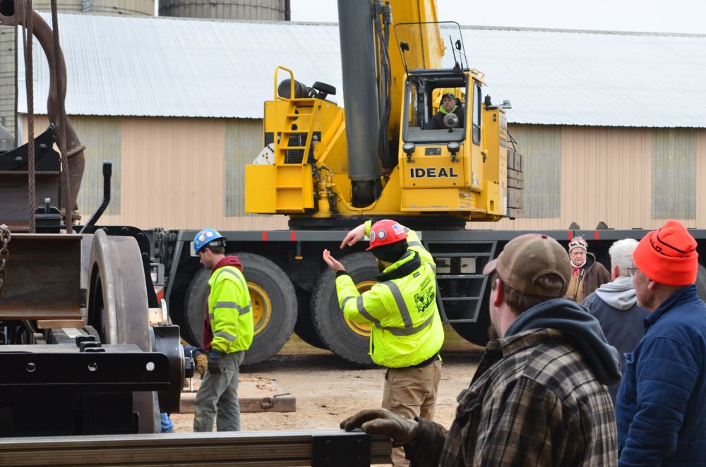
While the locomotive was suspended in the air, ground crews slowly spun the the locomotive’s running gear 180 degrees. Completing this maneuver now will simplify steam-up tests later this year by making it so the locomotive will only need to be pulled forward by 20 feet or less to have the smokestack clear of the building.
-
- Suspended in mid-air, the ground crew begins to slowly rotate the locomotive.
-
- Halfway through its rotation, the running gear is gradually positioned over the newly-built panel track.
Mike Wahl, 1385 Project Manager (Left), and Steve Roudebush, owner of SPEC Machine (right) check the locomotive’s alignment before it begins its decent down to the rails.
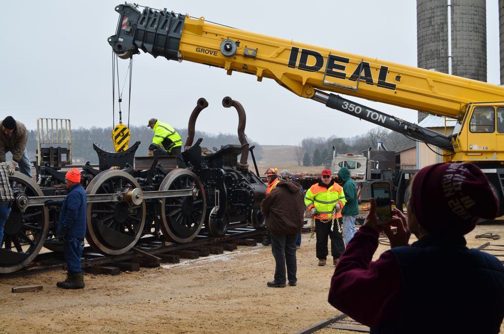
With seeming ease, the crane operator lined the locomotive directly over the track and gently lowered it onto its own wheels once again – the whole operation taking only a couple minutes once the wheels were off the ground.
-
- Brett Morley (center), the project’s boiler engineer inspects the running gear before it is lowered.
-
- The crane operator takes commands from the ground crew.
-
- Safely on the ground, volunteers begin removing the lifting cables. SPEC Machine, located at an active farm, is an odd yet appropriate locale to restore a granger road locomotive.

-
- Bobbie Wagner, an MCRM board member, snaps a photo of the activity. Also in the photo are two additional current and one former MCRM board members.
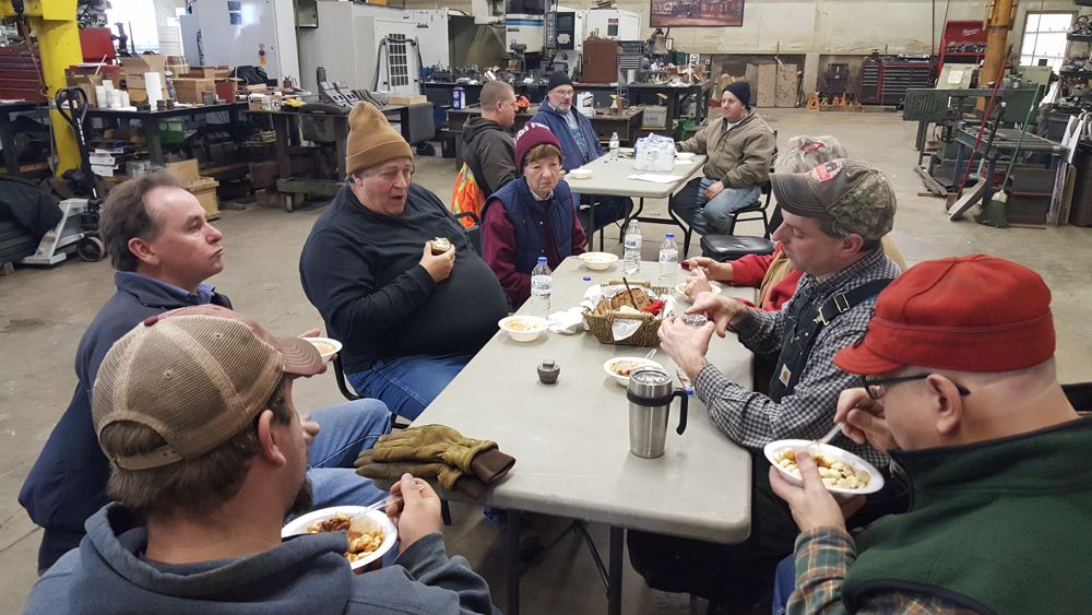
With the locomotive back on the rails, volunteers and crane crew went about removing the cables and attaching a custom made drawbar to allow a tractor to tow the locomotive inside its new berth. With the job complete, the crew disassembled the temporary panel track and headed into the shop for a chili lunch and to make plans for the next work session.
-
- Volunteers unbolt a section of panel track.
-
- Post-crane lift group lunch in the shop.