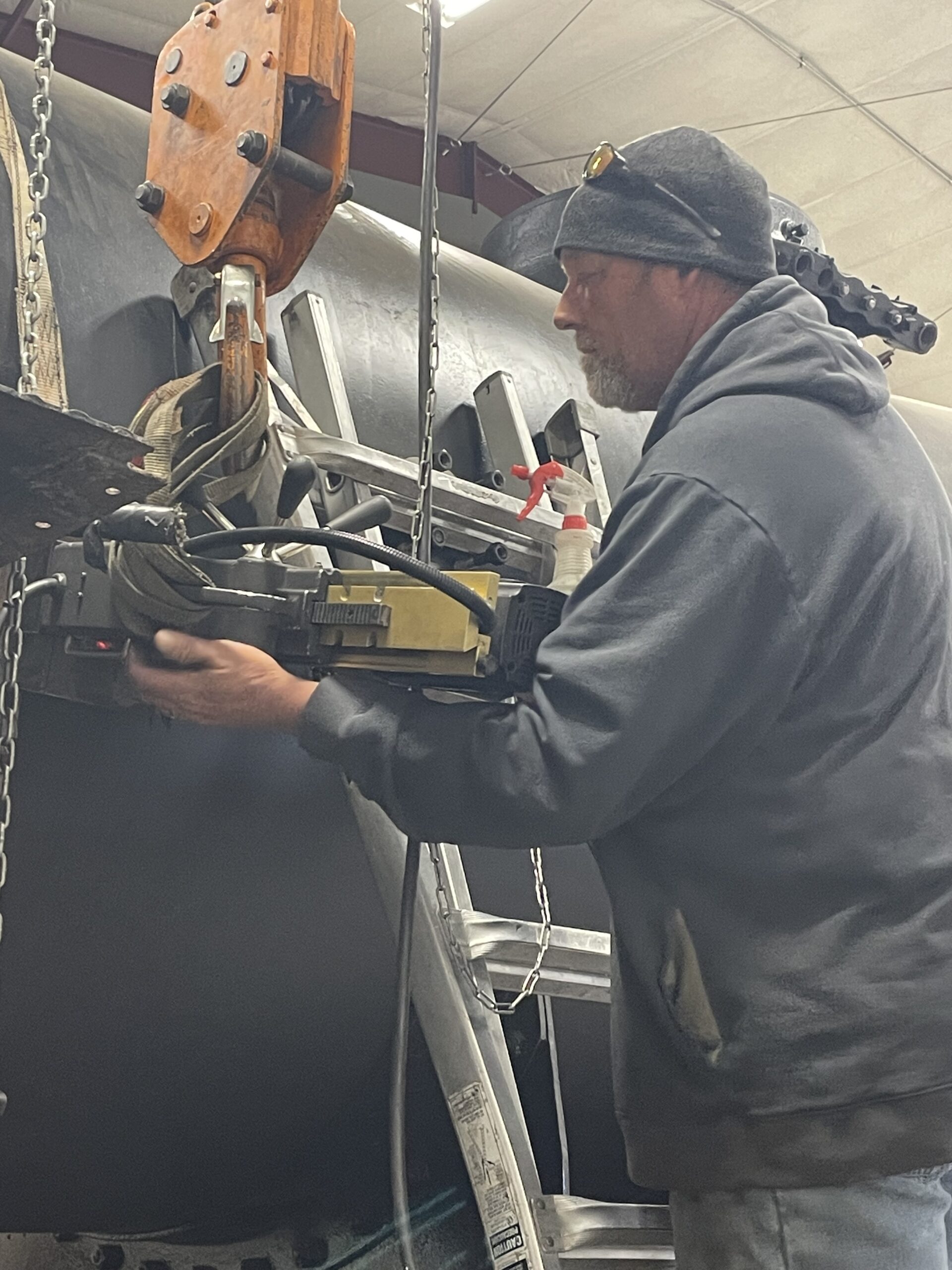
The runboards and handrails on a steam locomotive are necessary appliances that allow the crew to inspect and service many other appliances attached to the boiler. These include the locomotive’s air pumps, bell and ringer, sand dome, and generator. On the Chicago & North Western no. 1385 an extension of the runboards also becomes the cab floor/support so the 3-D puzzle-solving of the locomotive’s reassembly stage continues. For this update, we’ll stay on the runboards and address the handrails in the near future.
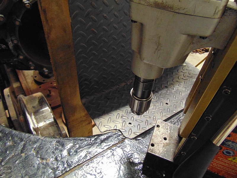
Installing the runboards and handrails now is important for two reasons. First, every bracket, support, or stanchion is attached to the boiler with studs and each of those studs requires another hole in the boiler to be drilled and threaded. As part of the Federal Railroad Administration (FRA) inspections to bring a locomotive back into active service, the boiler is pressurized with water and every penetration of the boiler must be tight and with no leaks. This inspection using pressurized water is called the hydrostatic test and must be passed before we can fire the boiler for the initial steam tests.
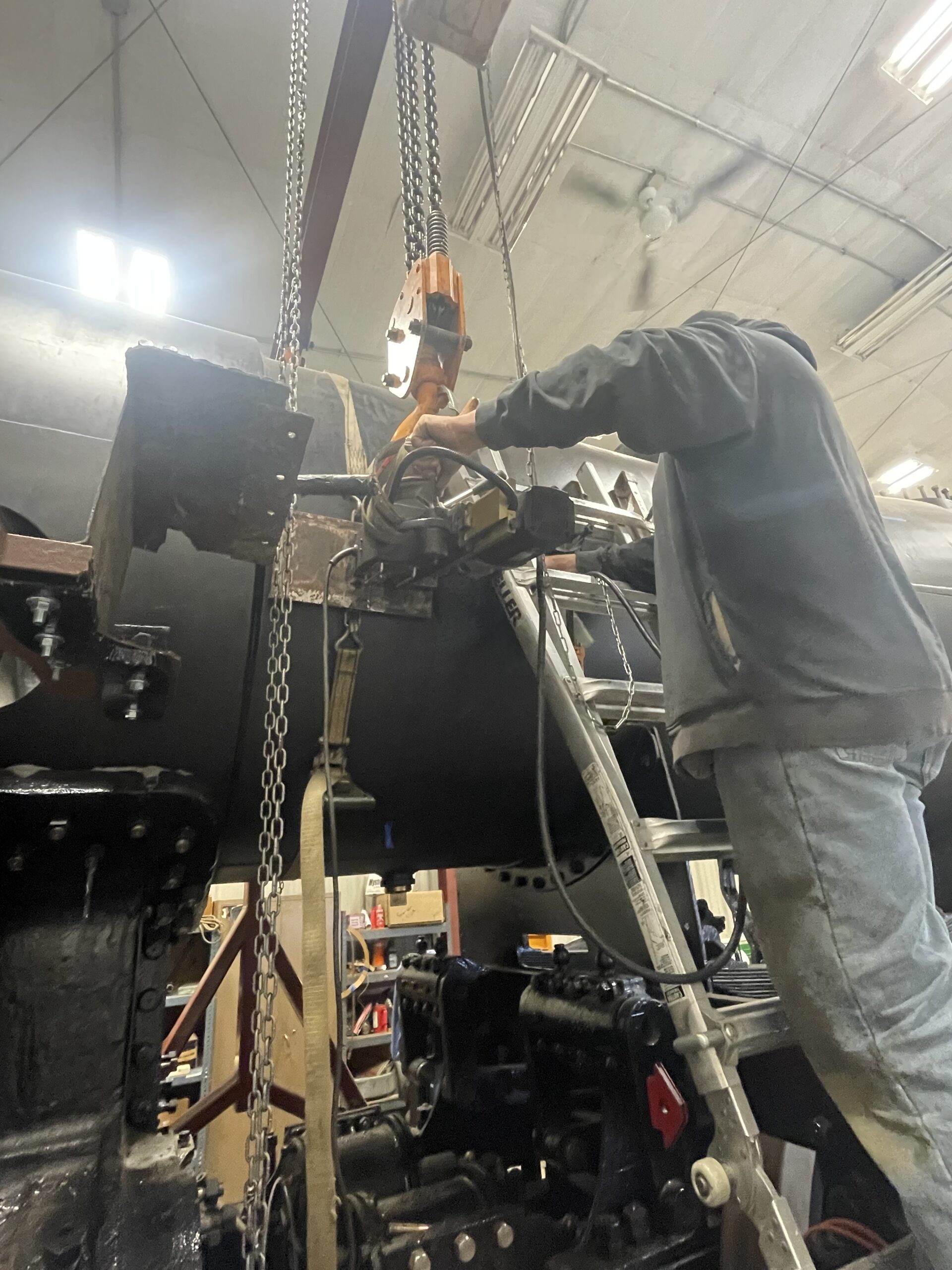
The other major reason for installing runboards and handrails now is it will make the remaining work on the top area of the boiler much easier. It will also make access much safer with a more stable platform to use.

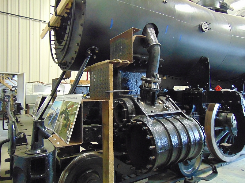
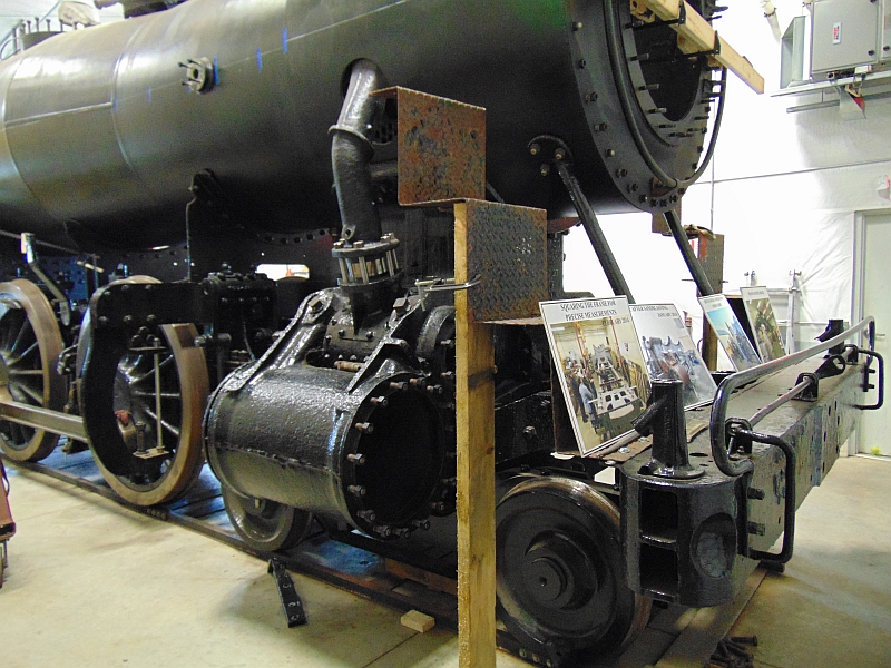
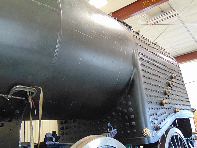
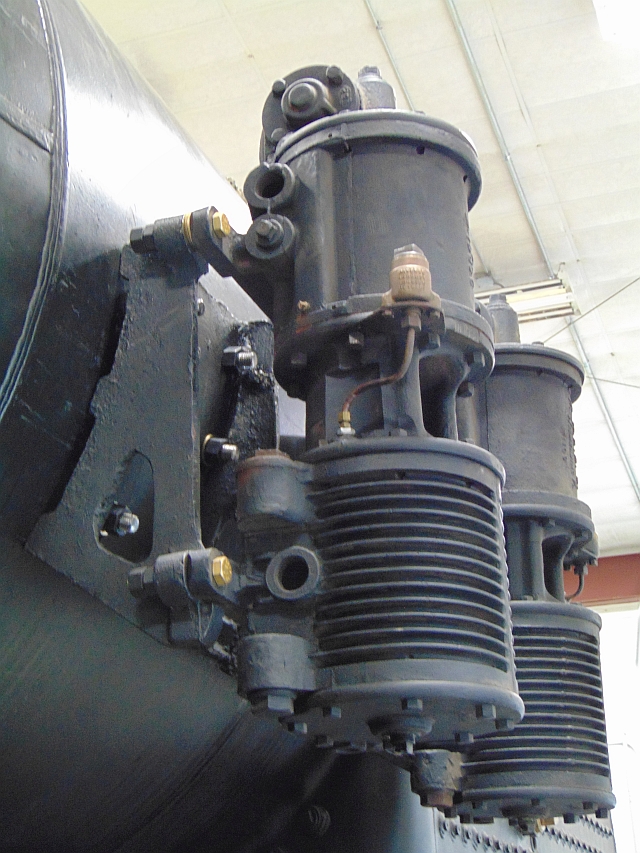
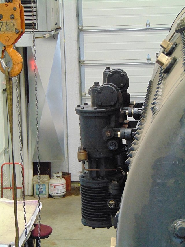
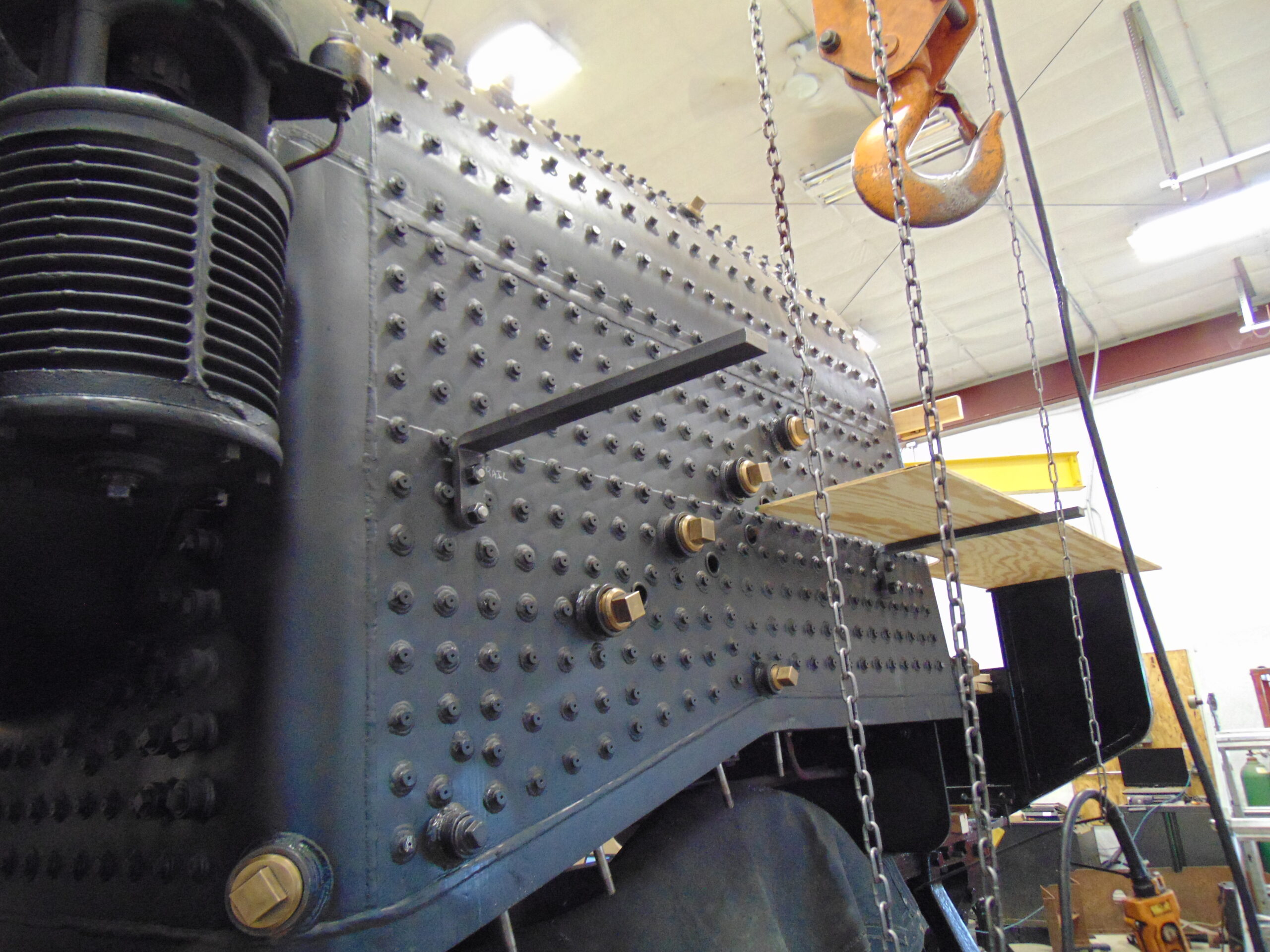
There are a pair of brackets on the smokebox that hold the lower step over the cylinders and then a pair on the boiler proper. The front pair of brackets on each side of the boiler proper are tasked with double duty.
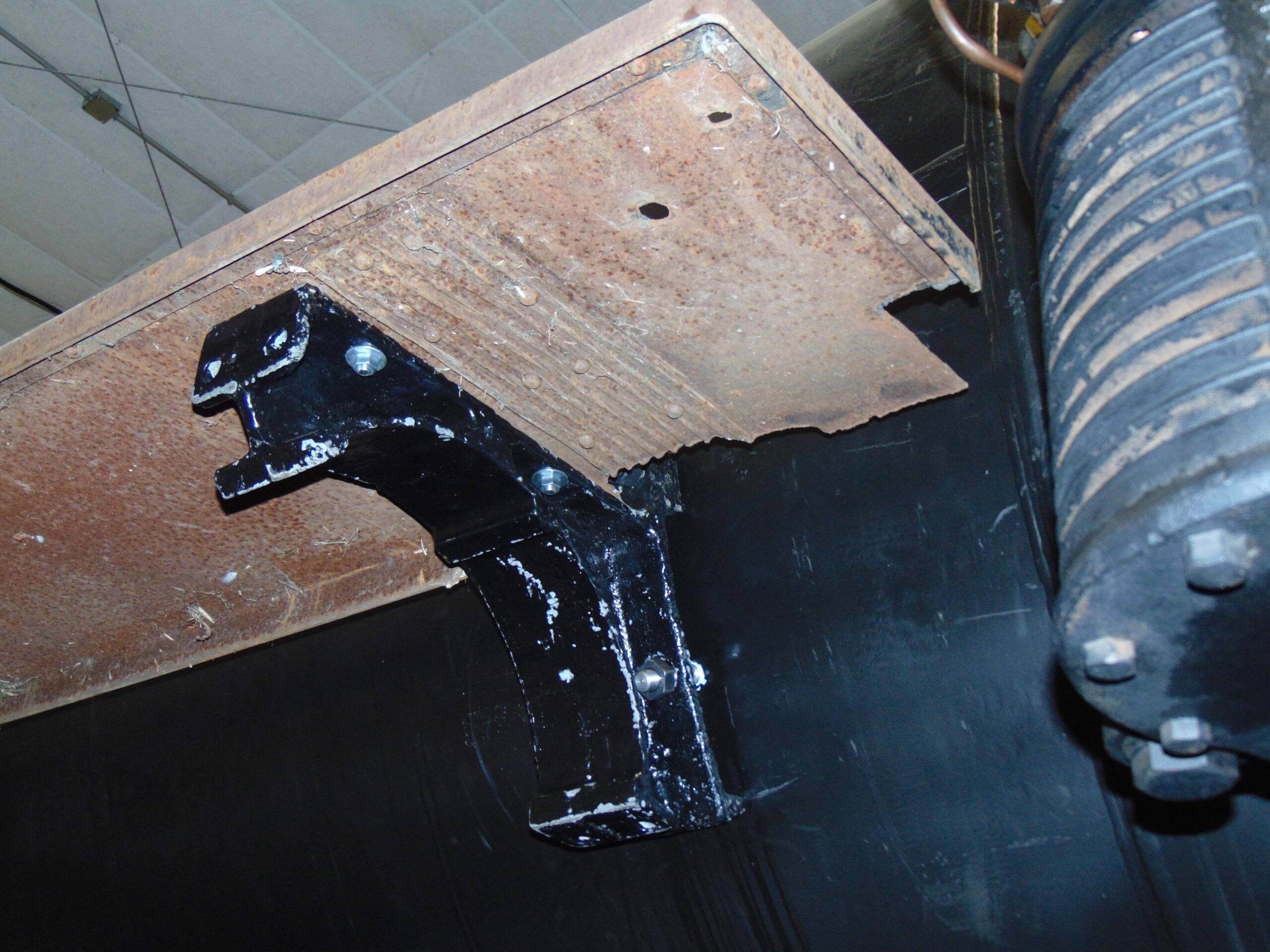
They are also the mounting brackets for the air reservoirs which account for their size and shape. The reservoir is held into the crescent shape by a pair of straps that go around the tank and then are bolted to the top & bottom of the bracket.
Behind the air compressors, two brackets are studded to the firebox sidesheets which will hold the runboard and the front of the cab while the rear of the cab is held up by a bracket on the end of the engine frame.
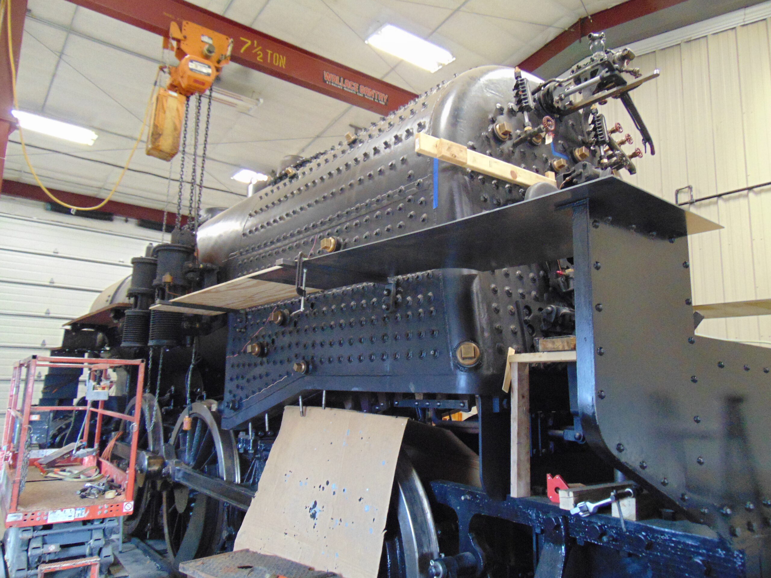
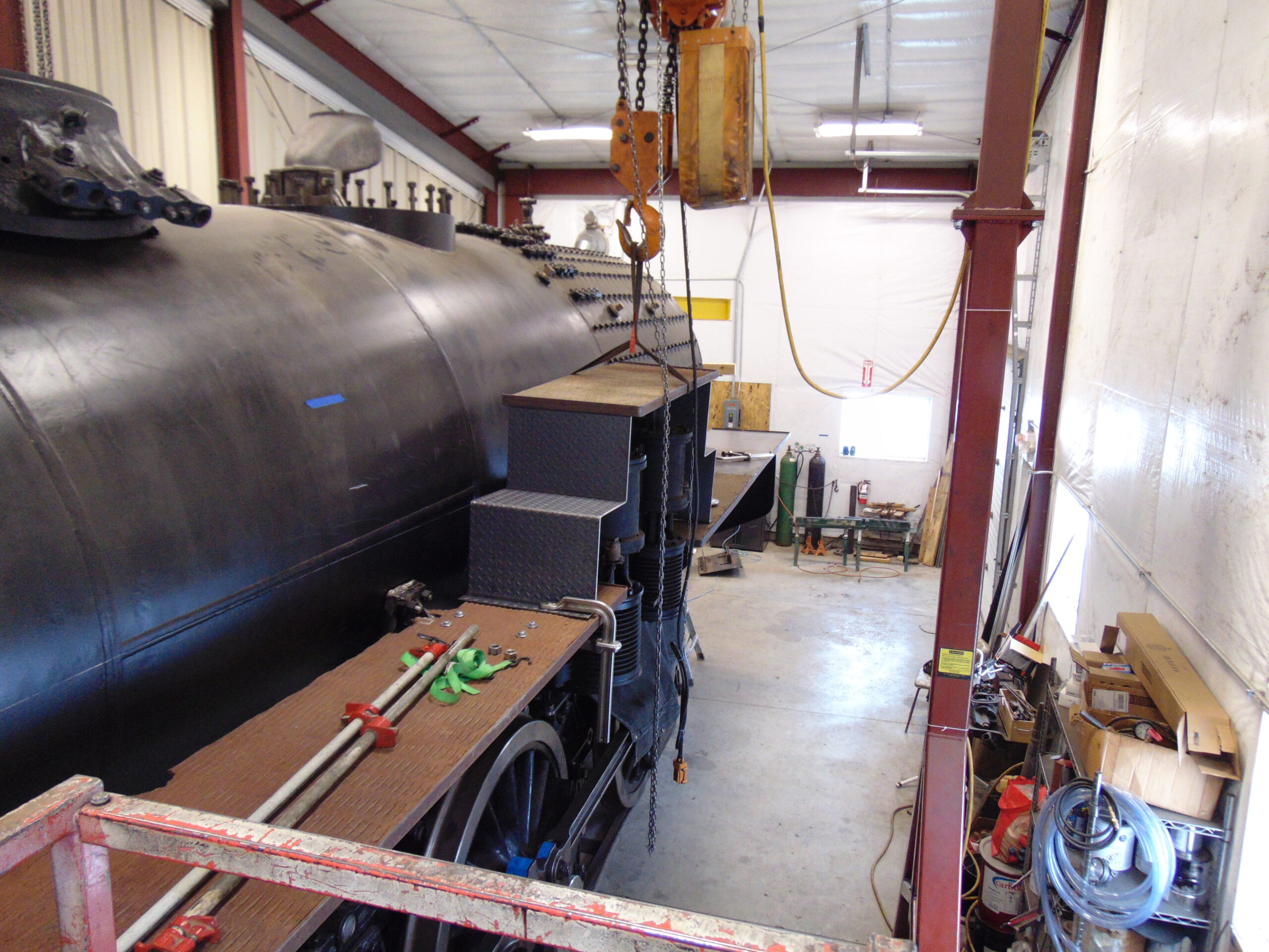
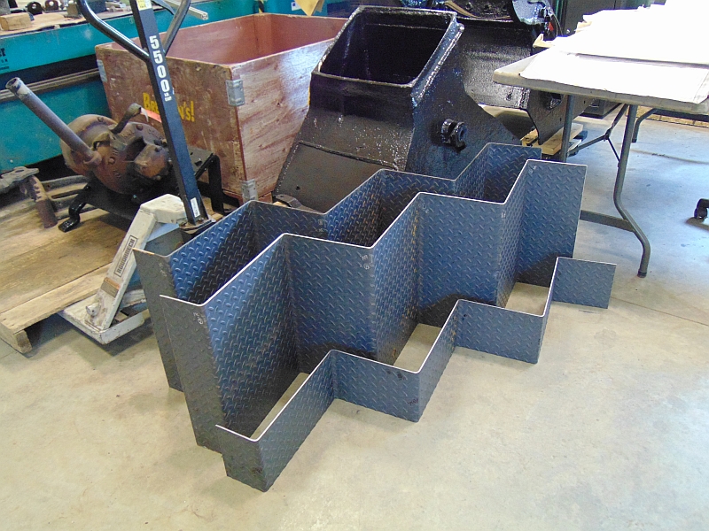
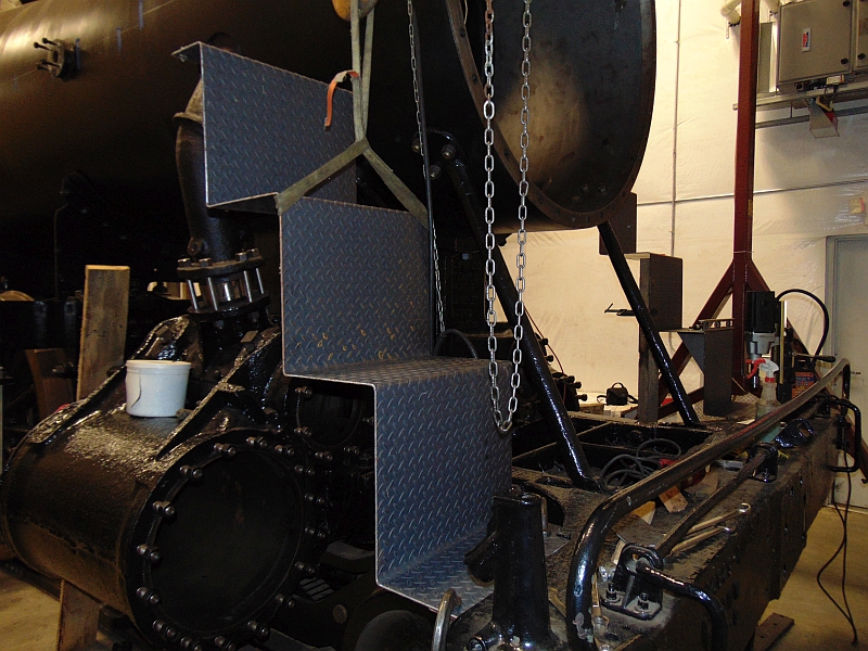
On the left side of the locomotive, the next parts added for fit-up include the steps over the air compressors and the rear portion of the runboard/cab floor.
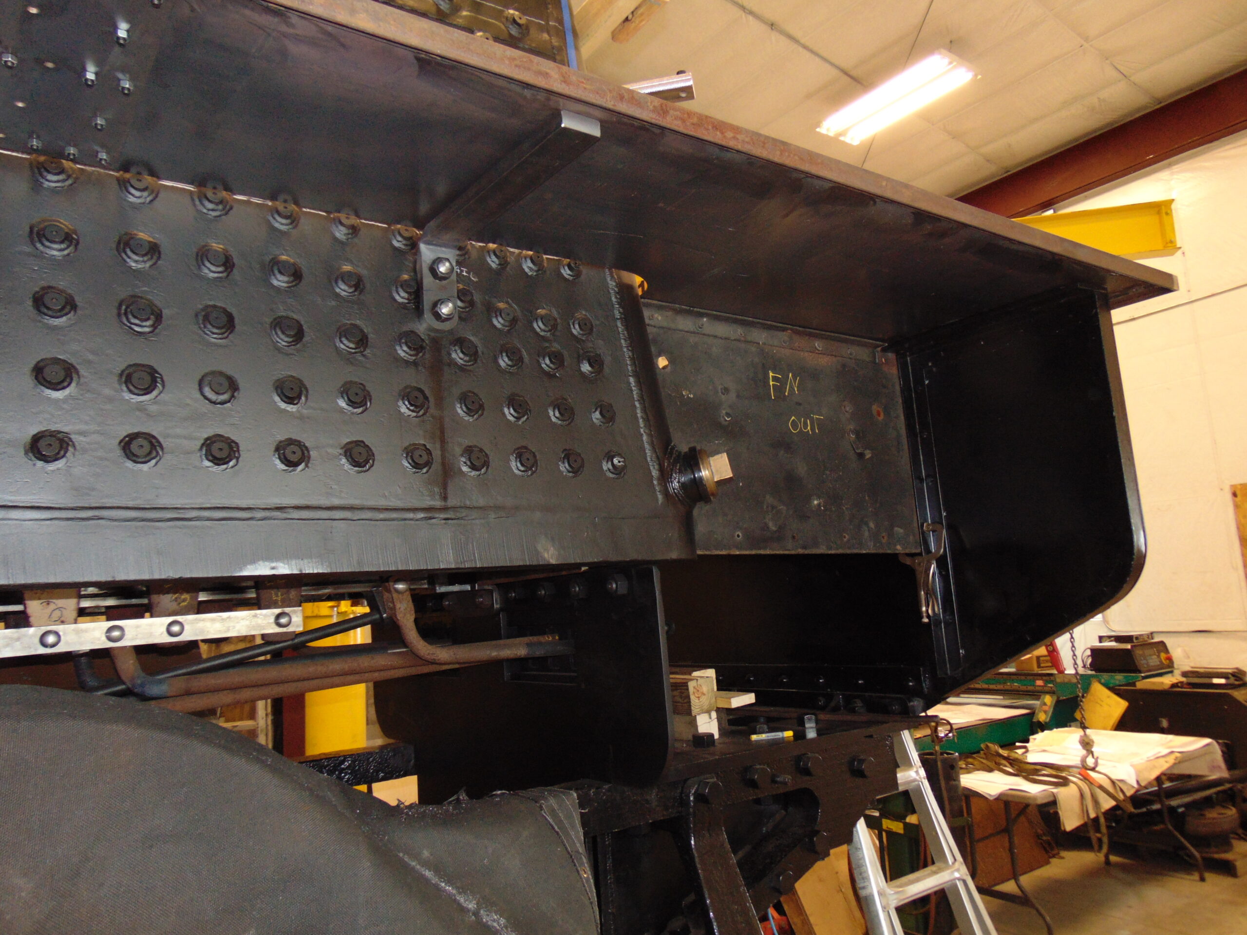
Also, in place for fit-up is the lower cab wall that closes in the space between the runboard and the firing deck.
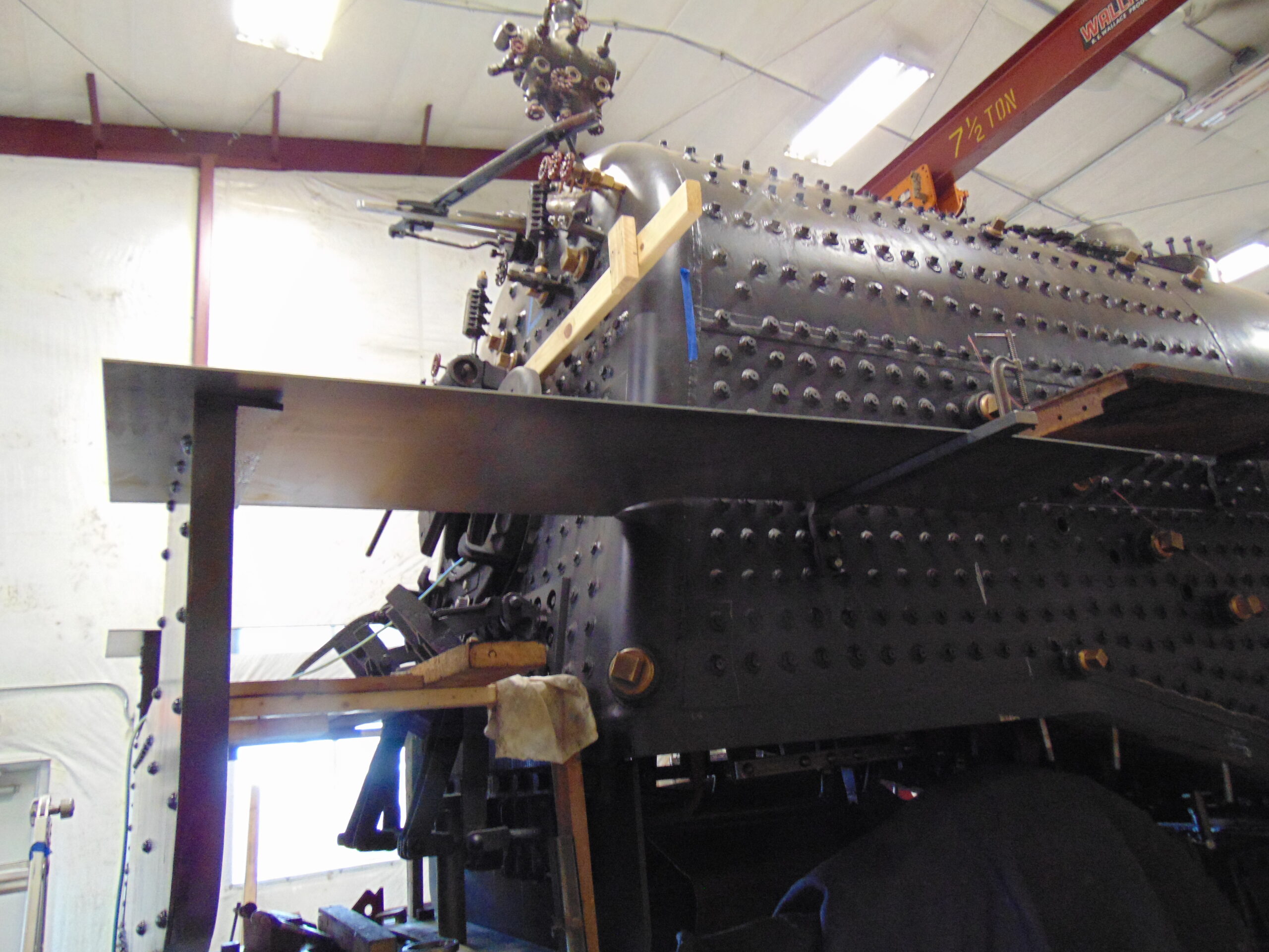
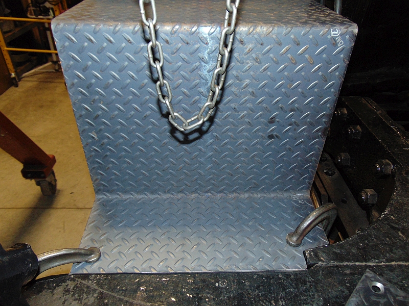
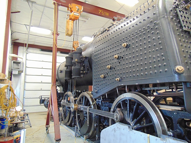
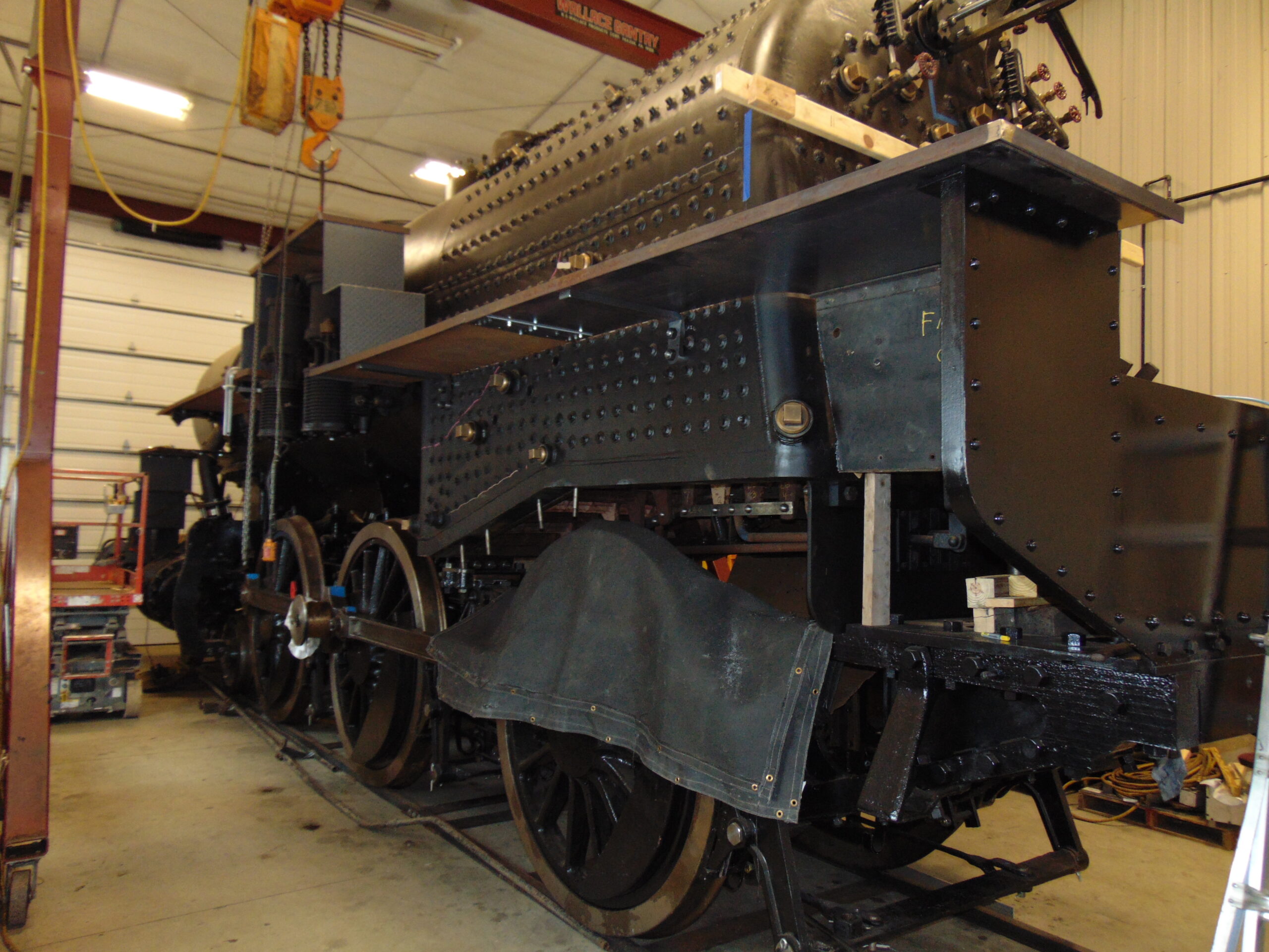
Moving to the right side of the locomotive the process is much the same except that at the forward edge of the cab the runboard is a bit higher off the rail than on the left side.

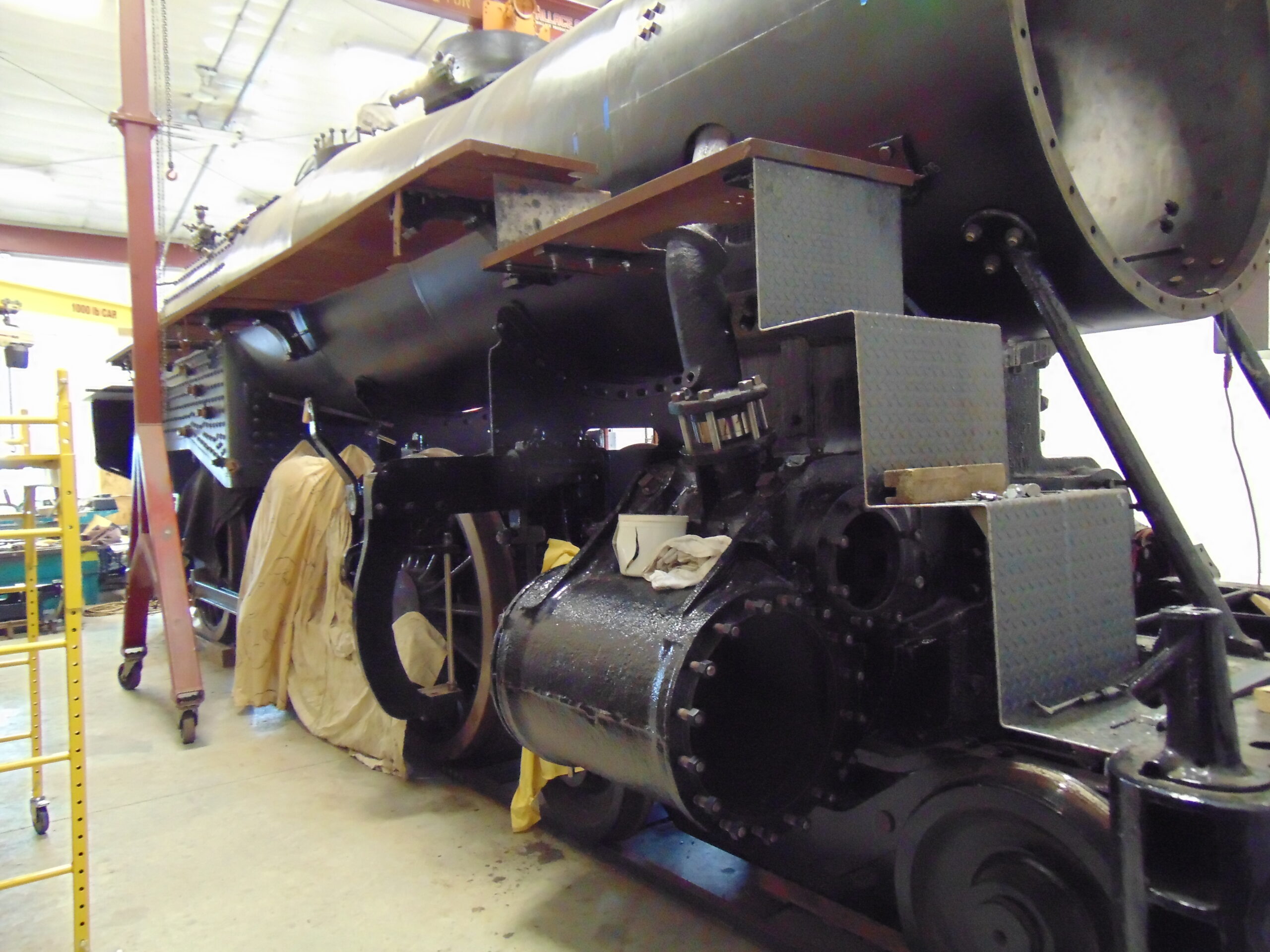
The rest of the right side is much simpler in that it is a single level. The forward runboard brackets here, too serve as brackets for one of the main air reservoirs.
The fit-up process is a work in progress but is moving us ever closer to the boiler hydrostatic test and then steam test.
All photos courtesy of M.L. Deets.