Welcome to the Chicago & North Western #1385 steam status blog! Follow along as we bring the 1907 American Locomotive Company 4-6-0 steam engine back to operating condition.
Mid-Continent Railway MuseumPosted on by Jeffrey Lentz
The next item to be mounted to the backhead of the 1385 is the hydrostatic lubricator. That is merely a complicated name for the device that delivers steam cylinder oil to the valves and pistons as well as to the steam end of the engine’s air compressors. Steam cylinder oil is specially compounded to mix with and then be carried by the steam to all the internal moving parts.
The lubricator lives in the cab of the engine within reach of the engineer so he or she can keep a constant eye on this vital function. If the oiling stops the engine will begin to make some really ugly noises in a very short time and if not immediately corrected those noises become quite expensive.
Once again the 3-D chessboard is set to mock up the placement of several pieces at once and the lubricator is hanging from the chain hoist. The bracket for the lubricator is mounted using 2 studs and its position is being verified between the try-cocks, throttle and one of the two required water gauge glasses.
A chain hoist is used to hold the lubricator in place during test-fitting.Placement of the lubricator bracket between the try-cocks and water glass.
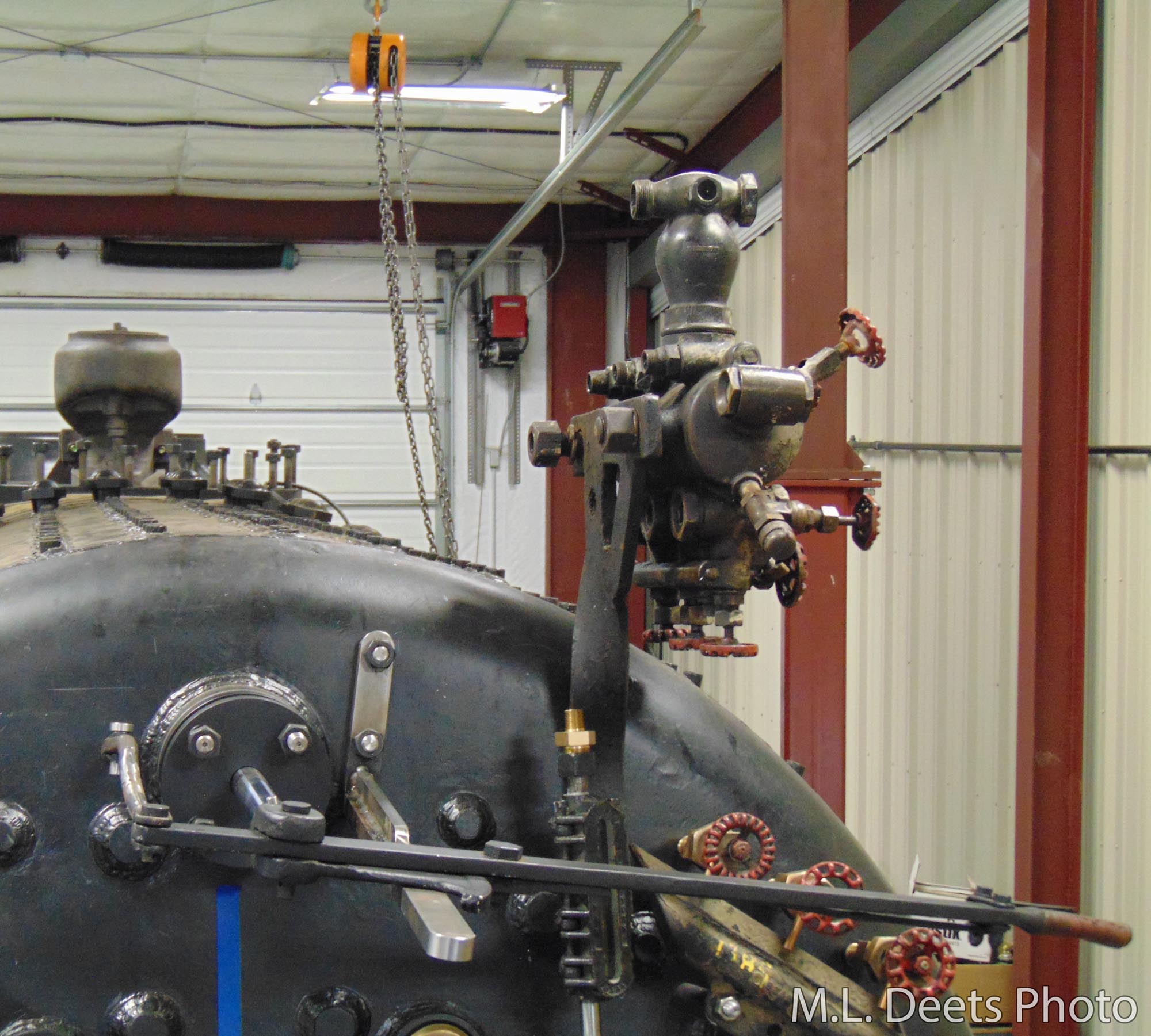
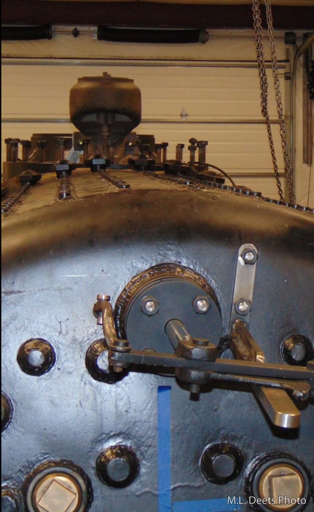
Here is the lubricator mounted in its final position showing how it is studded to the boiler. Our parting shot shows the upper right corner of the backhead and the top of the boiler with the body of the throttle peeking up out of the steam dome area. The dome was made to be removable to better facilitate maintenance work in the future.
Hydrostatic lubricator installed.Hydrostatic lubricator with top of boiler and throttle in view.
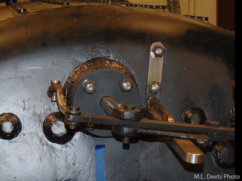
One of the next steps at SPEC Machine has been to finish the installation of the throttle rod and handle on the backhead of the boiler. Many of the new parts were shown in the December 25, 2020 update and now they have found their final home. The chromed end of the throttle rod has been mated to the long reach rod and is being fed through the boiler to the throttle proper. The half-lap and bolted connection is per the C&NW drawings and replaces the threaded coupling that was found when the throttle rod was disassembled.
Throttle rod installation in progress.
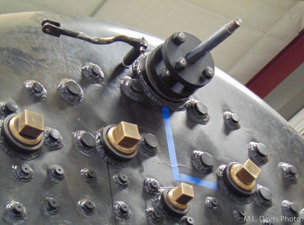
The packing gland was installed to properly position the rod so the throttle handle anchor could be properly located and studded to the boiler per the C&NW drawing.
Throttle packing gland and throttle handle anchor installed.
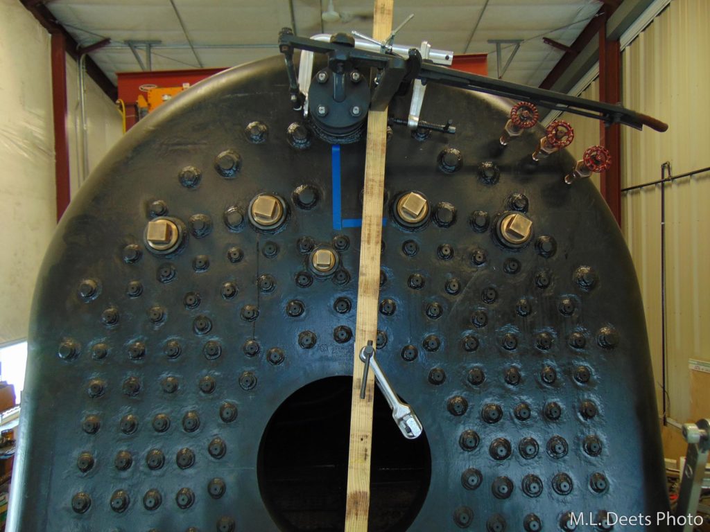
As another part of the 3-dimensional chess moves, the throttle handle support was mocked-up to check not only for correct placement of the handle but also proper clearance over the gauge-cocks and around the boiler stays.
Throttle handle support mock-up to check for clearances.
The original support was an “L” shape with the short leg pointed down. The new support has the short leg pointed up because the new boiler has a stay rod in the way of the old mounting. Here is a look at the completed assembly with the support studded to the backhead. The anchor does have a dog-leg in it per the C&NW drawings. It also does connect squarely at the stud end even though the camera lens distortion makes it look differently.
Throttle support.
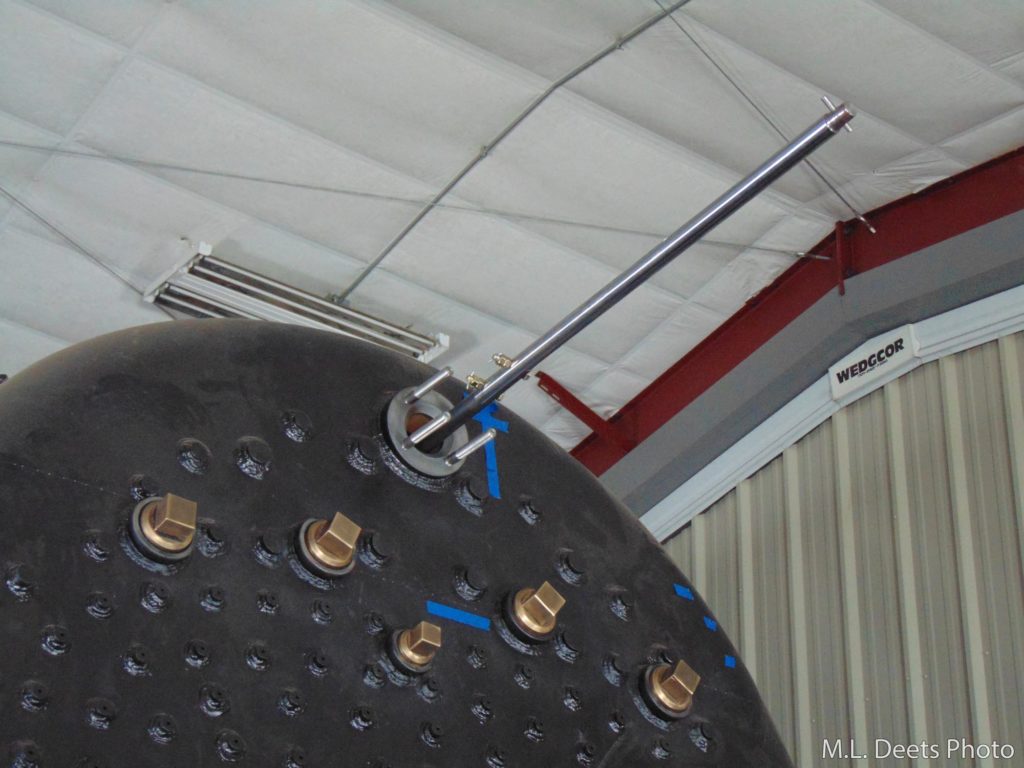
Last but not least is a look down the top of the boiler from the throttle handle down to the throttle itself.
View of both the throttle and throttle rod.
In the next update: Installing the hydrostatic lubricator
Mid-Continent Railway MuseumPosted on by Jeffrey Lentz
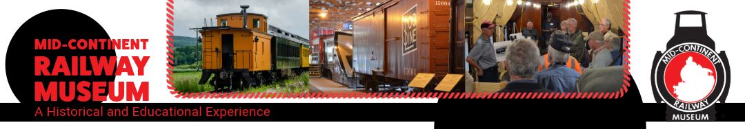
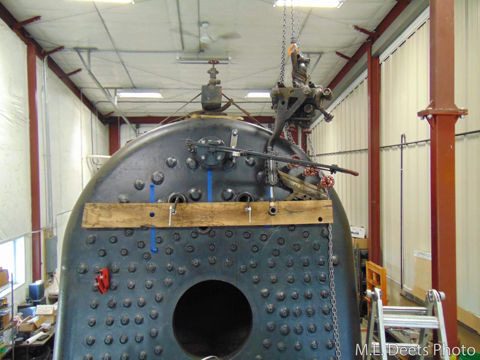
The latest accomplishment on the 1385 boiler has been the installation of the Try-Cocks. That is the proper name of an important set of monitoring and safety devices. In previous posts the question “What’s the first 3 things to know about any boiler?”, was asked and the answer is still “Where’s your water?“, times three. It was also shown the highest point of the crown sheet was measured and marked. We are additionally required to install water level indicating devices whose lowest reading shall not be less than 3 inches above the highest point of the crown sheet.
Close study of the locomotive drawings has shown (Thanks, Ed) that the C&NW standard was to install the indicating devices to show not less than 4 inches of water, giving us an extra inch of safety margin. One of the types of indicating devices is a set of three Try-Cocks, so named because they allow the operator to “Try” the level of the water in the boiler.
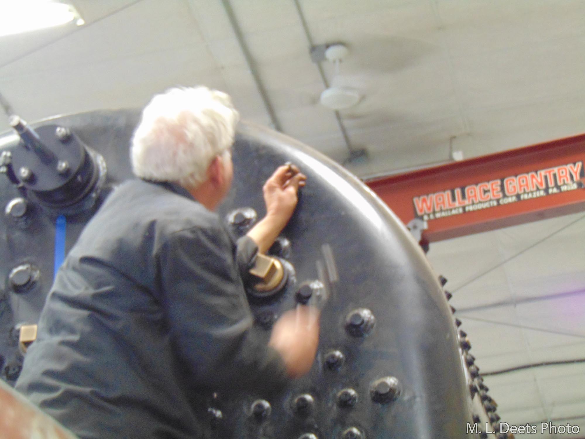
Punch marks indicating location of crown sheet are visible just above the blue tape.Steve R. of SPEC Machine adds punch marks for use with locating the Try-Cock.
In the first picture the punch marks showing the water side of the crown sheet can be seen just above the blue tape. Steve R. of SPEC Machine works so quickly it is sometimes hard to catch a clear picture as evidenced by the photo of him placing a punch mark to locate the center of one of the Try-Cocks. A hole is then drilled and threaded to accept the base or “spud” of each Try-Cock.
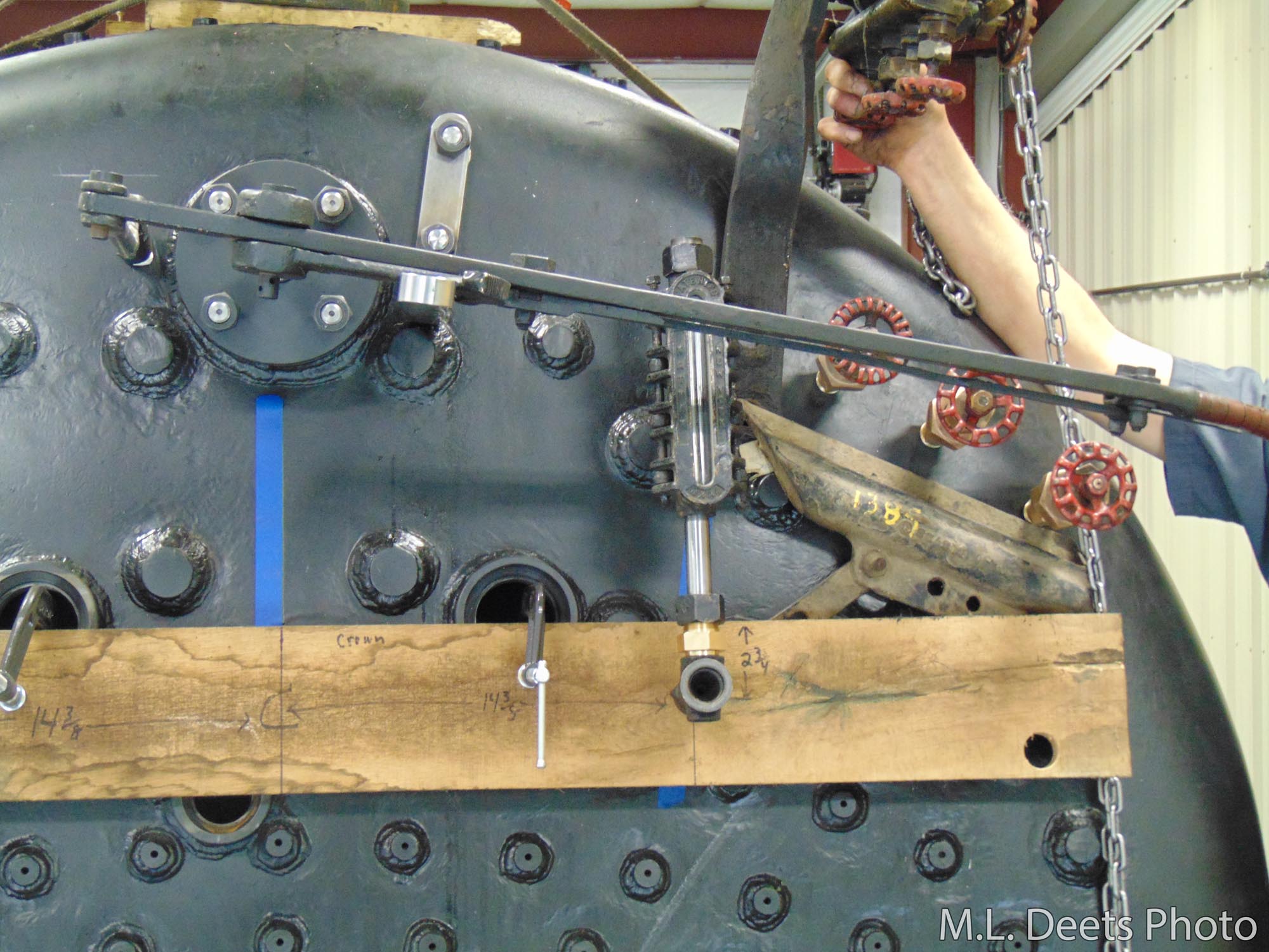
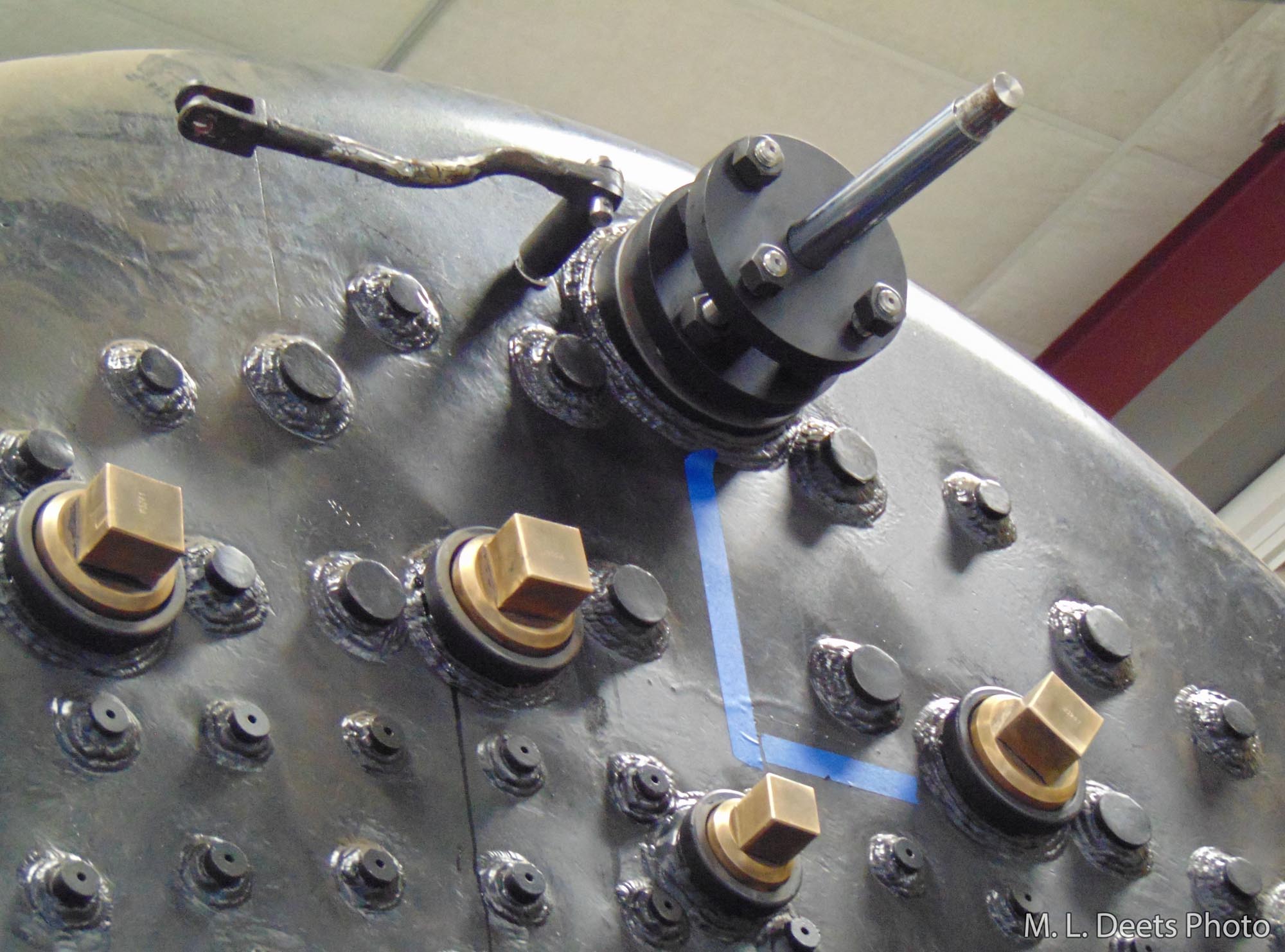
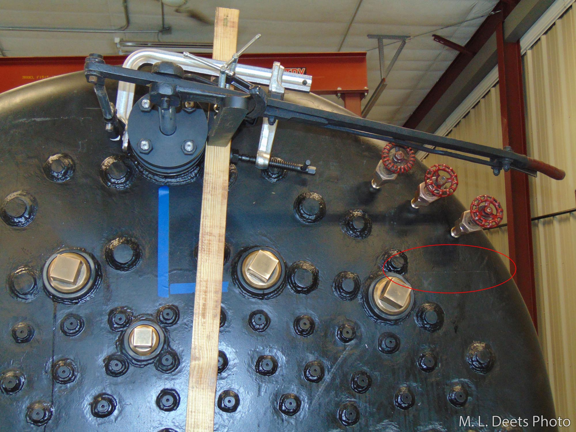
Checking the placement and clearance of the throttle and try-cocks.
The above shot shows all three in place along with a temporary placing of the throttle handle to check clearances. This is part of the 3-D chess necessary to make sure all the components will fit before they are installed. In the circle is a marking of the water side of the crown sheet so we can be sure the lowest Try-Cock is at the proper level.
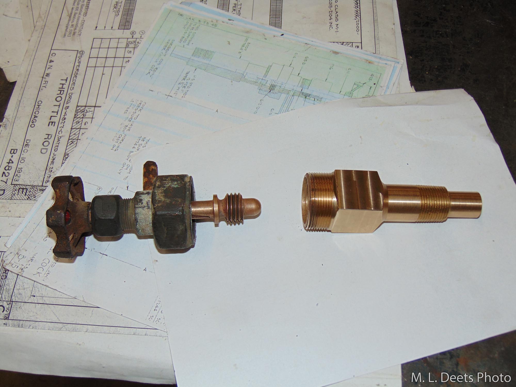
C&NW 1385 Try-Cocks. Bonnet and stems (left) are original. Spuds (right) are new.
The Try-Cocks themselves are a mixture of new and old. As seen here, the bonnets and stems are original to the 1385 but the spuds were machined from a new piece of code-compliant material. This was necessary because the new boiler has a reinforcing plate applied to the inside of the backhead in order to meet with the strength requirements of the current construction code. This means the steel in that area is much thicker than the original boiler and in order to properly reach far enough into the water space the spuds needed to be longer.
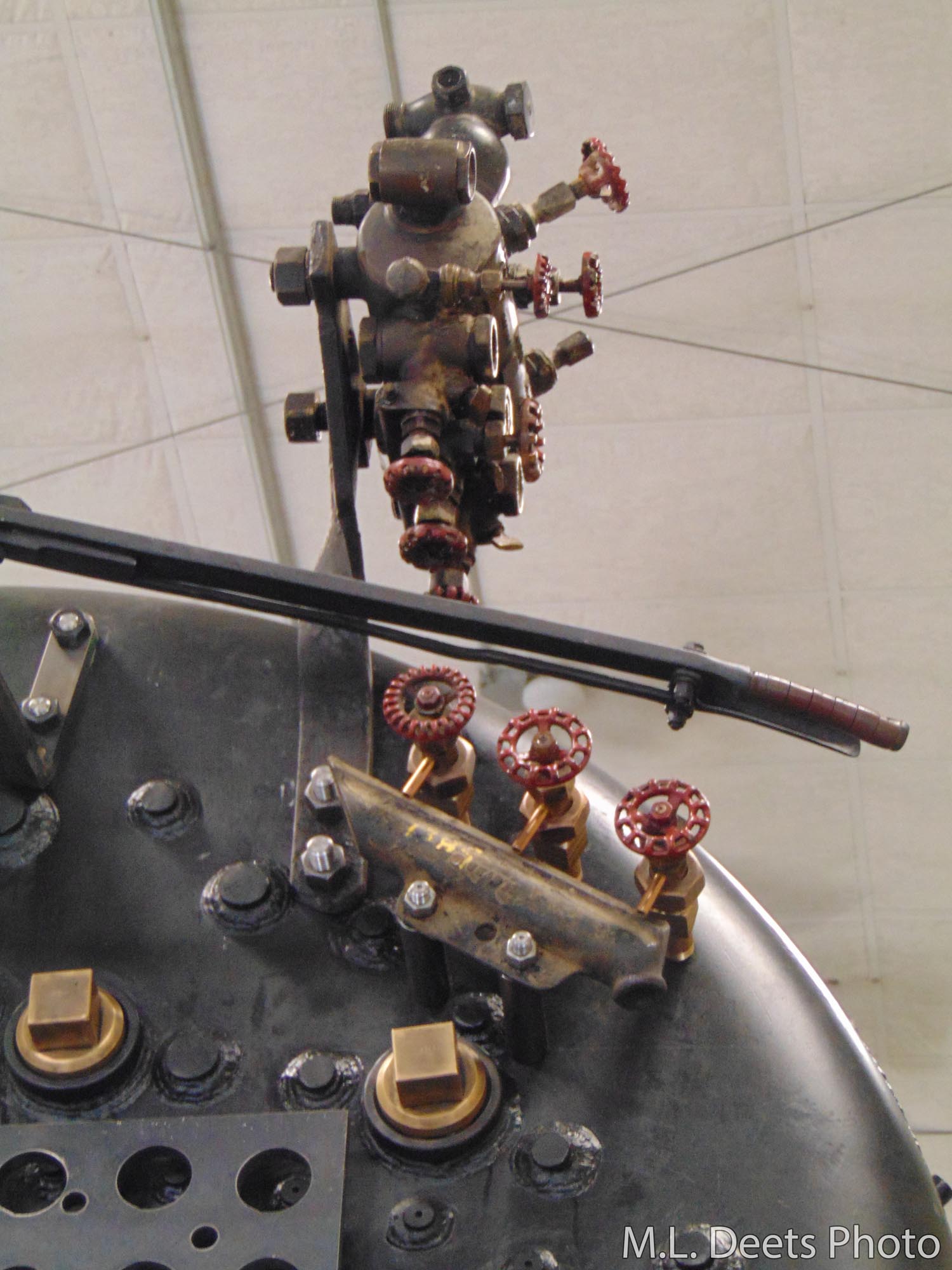
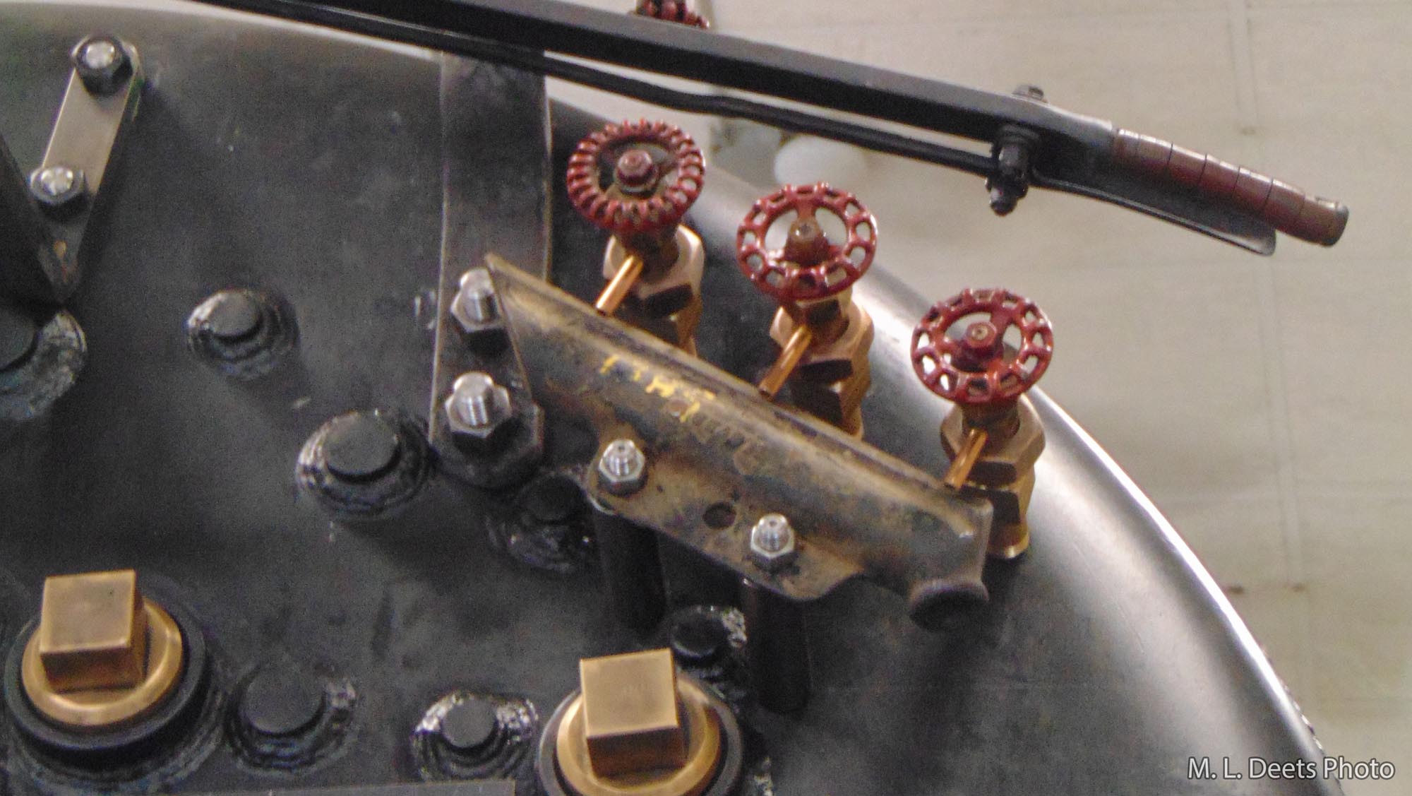
Each Try-Cock has a drain tube installed in the valve stem to direct the steam and water into the drain cup when the valve is operated to “Try” the water level. Below is how they look after final installation of the spuds, stems and drain cup. The drain cup will have a pipe that extends through the cab floor to drain the water out onto the right-of-way.
Final installation of 1385’s Try-Cocks, stems, and drain cup.
In Upcoming Updates: The throttle handle and rod as well as the engine lubricator.
Mid-Continent Railway MuseumPosted on by Jeffrey Lentz
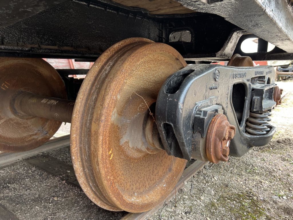
On April 23, 2022, a team of volunteers consisting of Kyle G., Ross S., Perry A. Richard P., and led by Ed Ripp, Mid-Continent’s newly named General Foreman of Steam Power, worked on jacking up the front of the tender and rolling out the tender’s front truck. While the truck was out from under the tender, the wheelsets were removed from the truck to facilitate inspection of the roller bearings.
The inspection was necessary due to flooding at Mid-Continent Railway Museum in 2018. The bearings were potentially reached by the floodwaters which could have led to corrosion on the bearing surfaces. To make sure no water damage had occurred, it was necessary to remove the wheelsets to allow for a full, detailed inspection. Fortunately, the inspection of the front truck wheelsets found no evidence of corrosion.
C&NW #1385 tender front truck. April 27, 2022.
The volunteers also made an adjustment to one of the shim plates so the plate will sit correctly against the tender frame. This work was able to be completed by evening.
Another volunteer work session will be forthcoming to inspect the roller bearings of the rear truck and possibly start installing fittings on the water ports of the cistern.
Mid-Continent Railway MuseumPosted on by Jeffrey Lentz
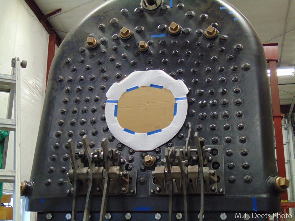
Our update of November ’21 covered what was going on with the grate installation inside the firebox. Here we will tie things up and cover the shaker mechanism & linkages. The shaker fulcrums are attached low on the backhead of the boiler near the mud ring. The cardboard over the firedoor hole is a mock-up for a needed spacer to allow mounting the firedoor over the staybolt ends. Detail on why is included below.
Firedoor spacer plate template.
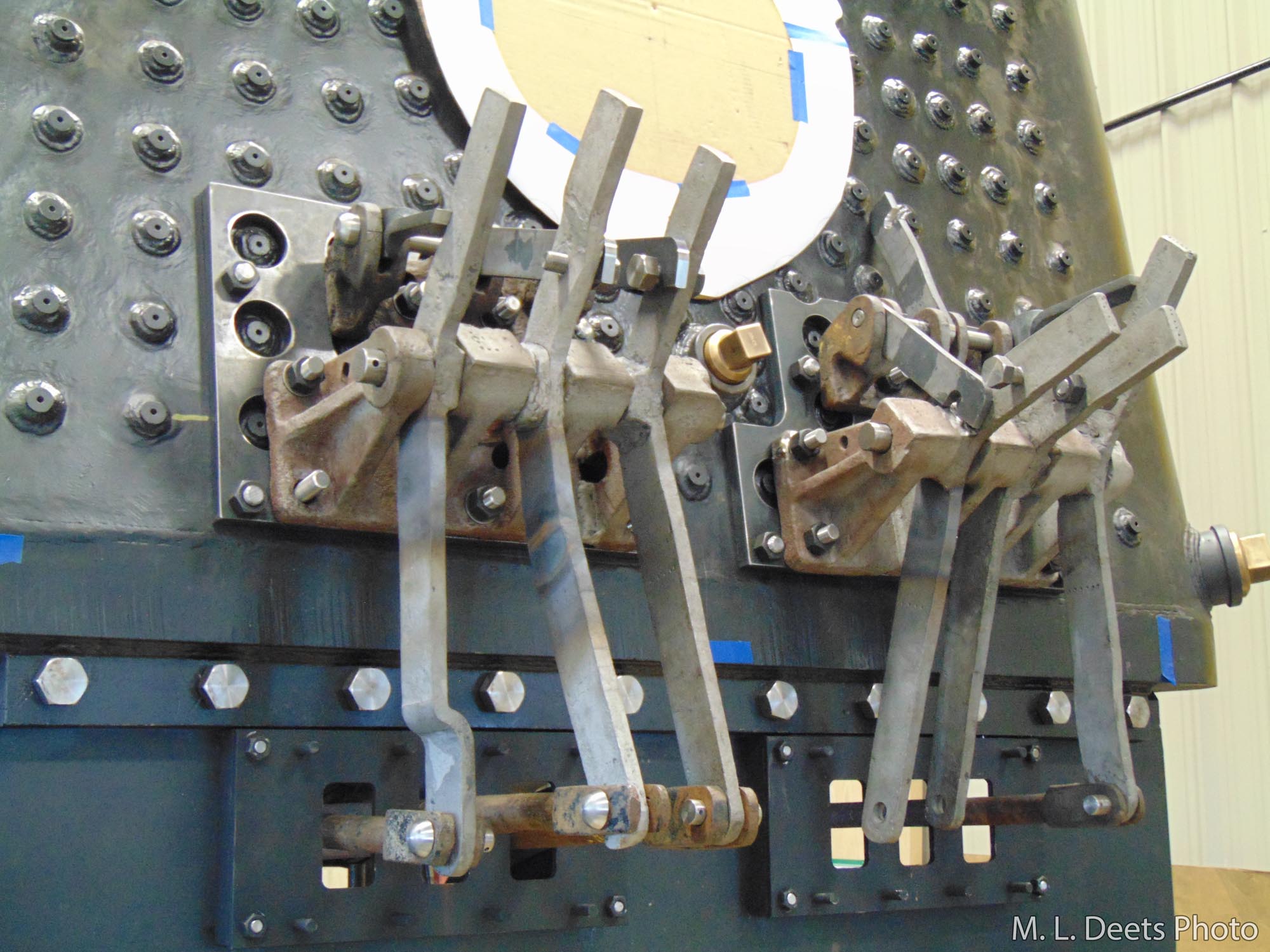
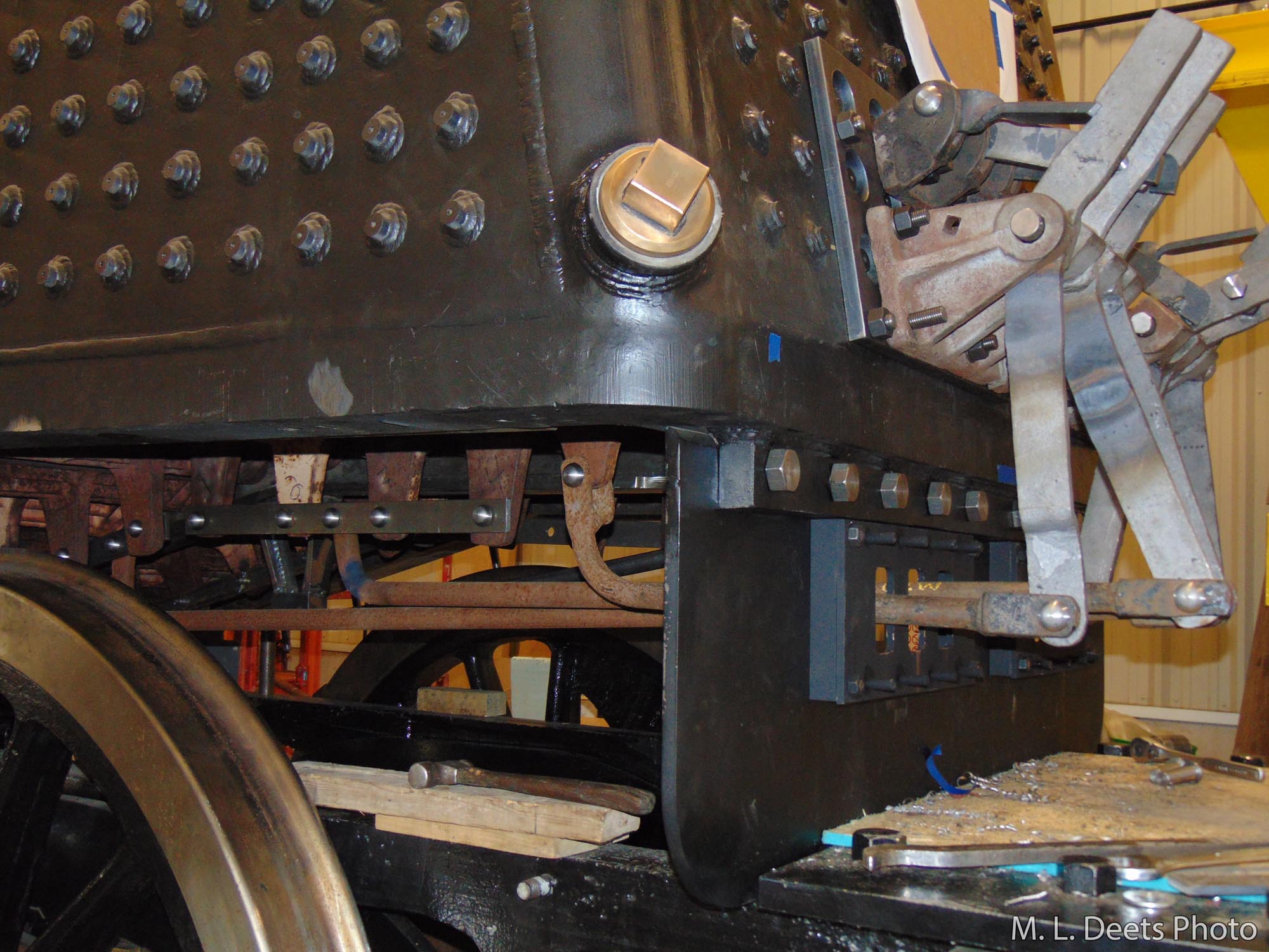
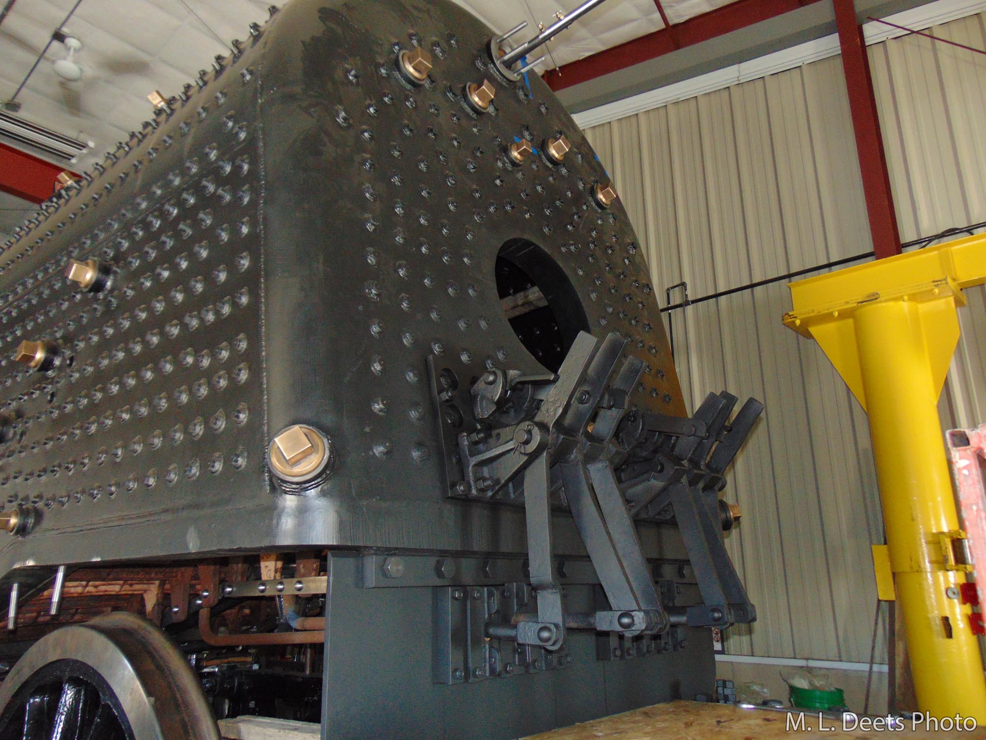
The shaker handle is slipped over the short stub controlling the section of grates to be shaken and the latch is released to allow the work to begin. The shaker rods reach under the boiler and connect to the tabs on the bottom of the grates in groups.
Grate shaker fulcrums.Grate shaker linkages.Firebox grates and grate shaker connections.
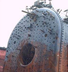
Because we are dealing with a new boiler of welded construction modifications are having to be developed and implemented. In the new boiler the welded staybolts stand out from the surface where the original construction used threaded stays which were hammered over during installation and resulted in an almost smooth backhead as seen in this shot from 2004.
C&NW’s old boiler with smooth backhead. 2004 photo.
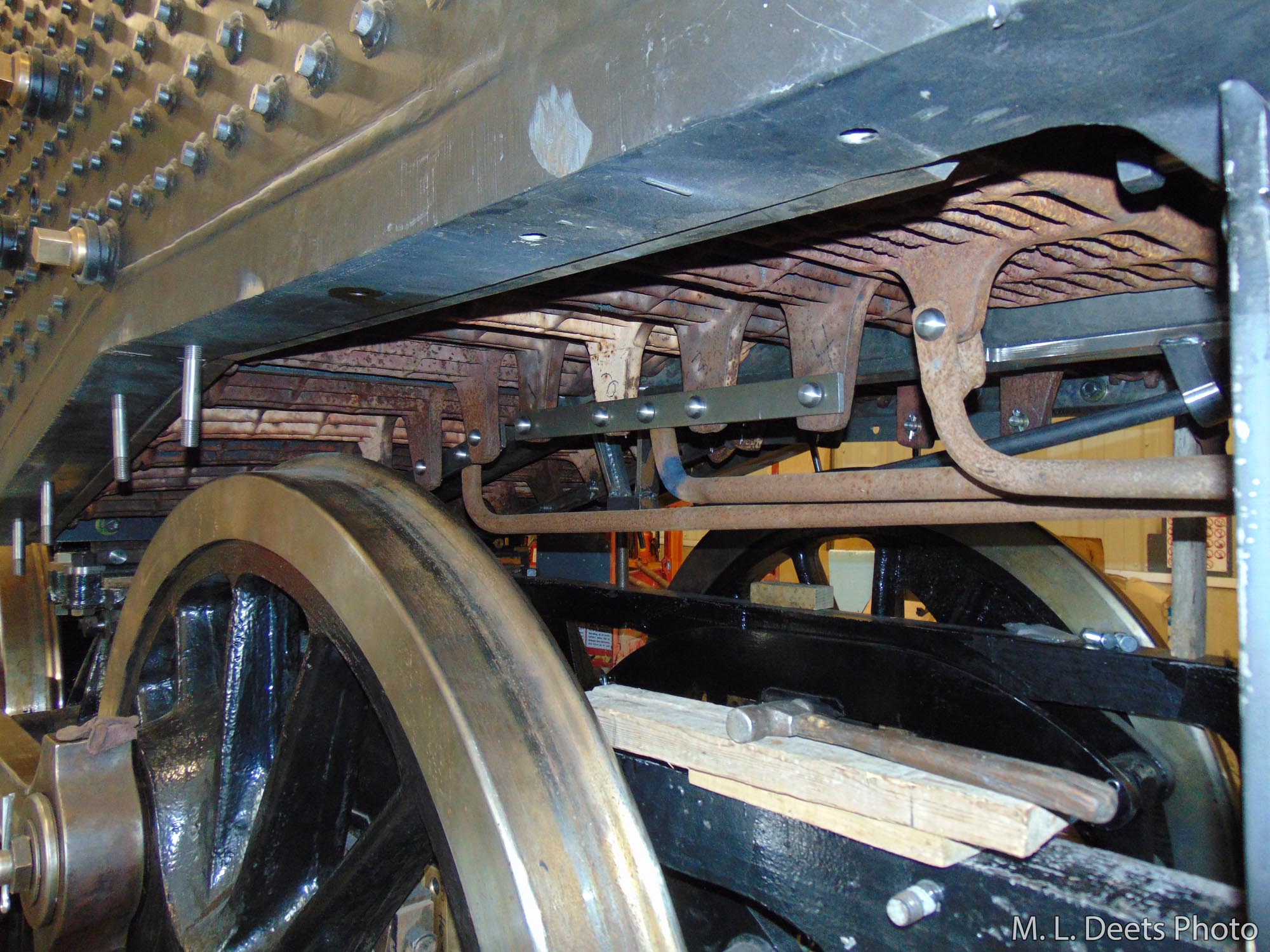
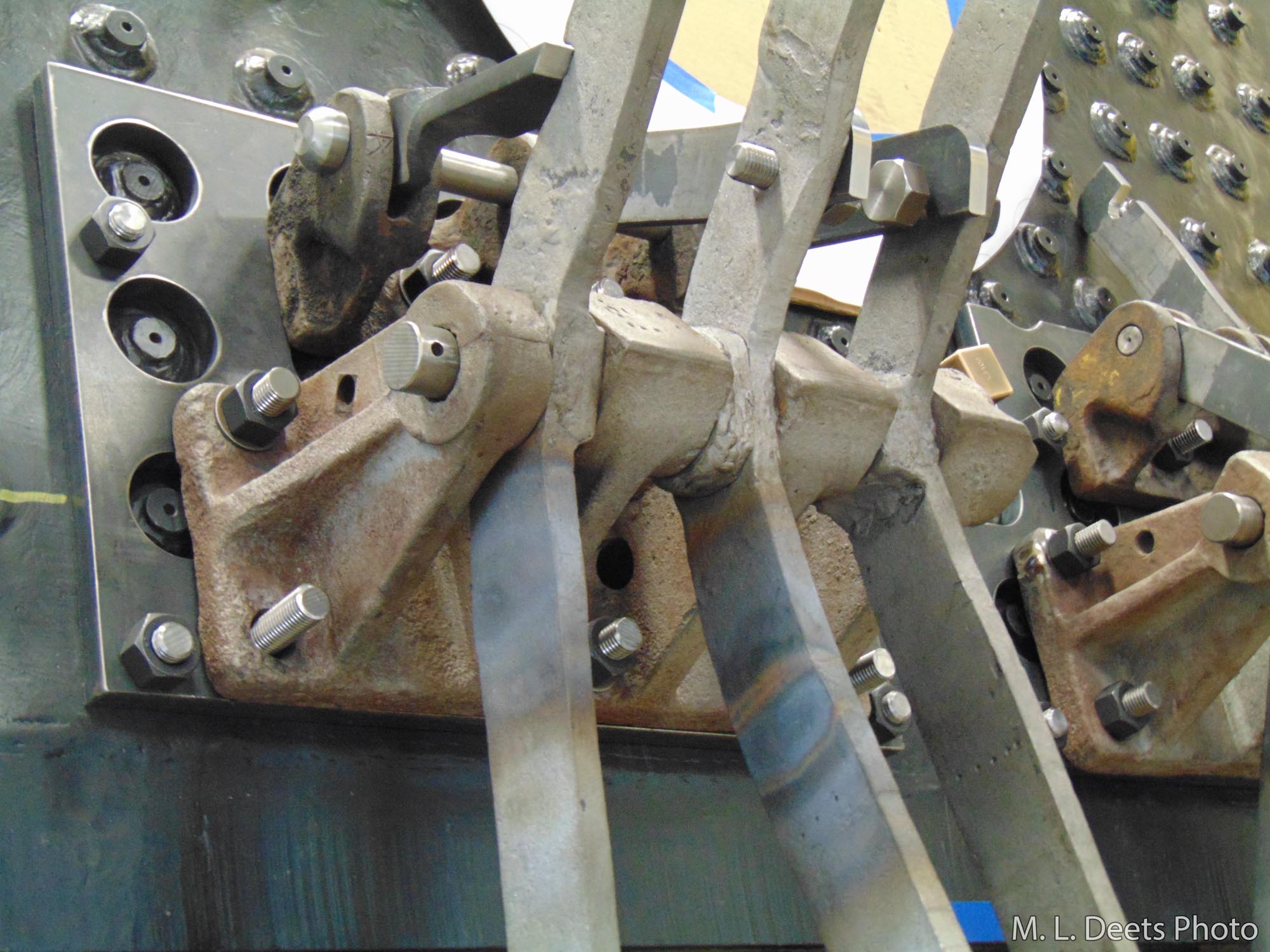
A spacer plate has been machined in order to give a smooth mounting surface for the fulcrums and you can also see new pins and latches have been fabricated. In the last shot we can see the grate shaker system fully installed and ready for the first fire.
Detail of spacer plate for grate shaker fulcrum.Fully installed grate shaker system painted and ready for use.