Mid-Continent Railway MuseumPosted on by Jeffrey Lentz
Continental Fabricators’ Tom G. supplied Mid-Continent Railway Museum with another new photo and a brief progress update on April 29th. Continental Fabricators is the shop hired to construct a brand new welded boiler for Mid-Continent’s Chicago & North Western #1385 steam locomotive.
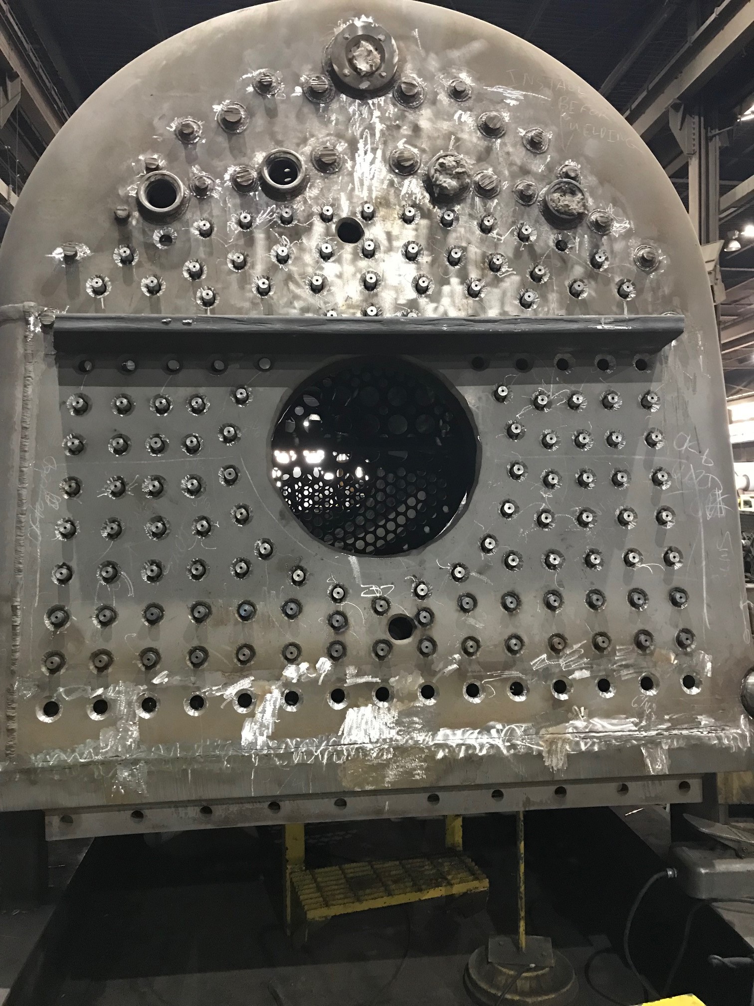
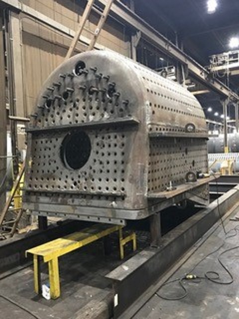
“Most of the backhead stays are fit as of this morning and they are beginning to weld. Stays in the sidesheets will be fit this week. The barrel is 60% welded.”
View of 1385 boiler backhead with most stays installed and ready for welding. The backhead is the portion of the boiler that extends into the locomotive cab. The large round hole in the center is where coal is shoveled into the firebox. Photo courtesy Continental Fabricators.
Mid-Continent Railway MuseumPosted on by Jeffrey Lentz
During the last week of January Continental Fabricators began installation of the 1385’s backhead diagonal braces. The backhead is the end of the boiler located within the cab and is a large, flat plate or sheet of steel that has been flanged and then welded to the wrapper sheet. Flanging is the process of very carefully curling the edges of a sheet to meet the next piece it will be mated to. The flanging process has been covered in previous update posts.
Much of the boiler is round, a naturally strong shape. With areas that are flat or nearly flat the forces of nature (including steam pressure) are constantly trying to force them round and thus they require support or “staying”. Staybolts, or “stays” and braces are thus used to reinforce the area and prevent the backhead as well as the other flat areas from bowing outward when the boiler is under pressure.
While installing these braces, crews at Continental Fabricators flipped the wrapper sheet/backhead assembly upside-down to facilitate easier working conditions. The first photo below shows the assembly as of the last week of January 2019 as the braces are being fitted and tack welded in place. The tack welds are just enough to hold the braces in place so this assembly can be righted and lowered onto the firebox/mud ring assembly to check for proper clearance between the braces and the firebox. Once Continental is satisfied with the fit-up between the pieces the wrapper assembly will once again be pulled off the firebox, inverted and the braces will receive the final welds.
Much of the backhead will be supported via staybolts connected between it and the firebox door sheet. The pictured diagonal braces are used to support the part of the backhead that does not line up with the door sheet and is instead connected to the wrapper sheet for support. This picture was taken during the last week of Jan. 2019. Photo courtesy Continental Fabricators.
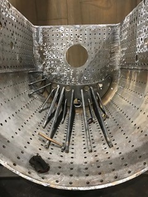
A few days later during this the first full week of February, Continental’s crews had flipped the backhead/wrapper sheet assembly right-side-up again and placed it over top the firebox/mud ring assembly. The purpose of doing this is to test fit for any contact between the backhead braces and the firebox crown sheet before final welding of the braces and before the wrapper sheet/backhead assembly is welded to the firebox/mud ring assembly. Once the two assemblies become one the installation of the staybolts can begin.
Test fitting the wrapper for proper clearance before completing backhead stay installation. Photo courtesy Continental Fabricators.
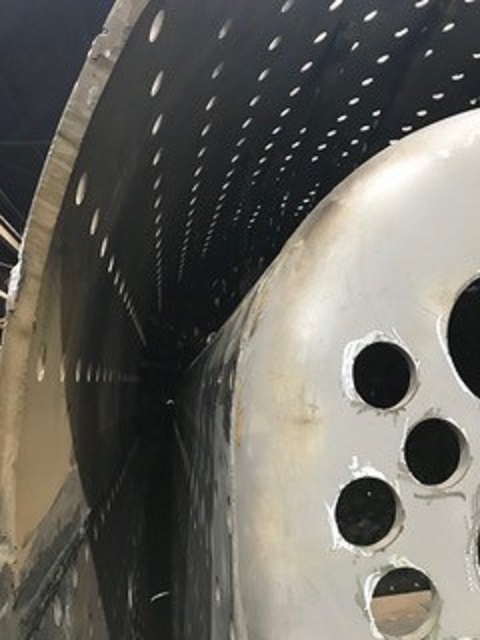
This photo was taken from the front of the firebox looking toward the backhead. It shows the steam/water space between the firebox/crownsheet and the wrapper sheet. Photo courtesy Continental Fabricators.
Mid-Continent Railway MuseumPosted on by Jeffrey Lentz
Gary Bensman and his team continued work flanging various sheets for the C&NW 1385’s firebox during the first half of April. Recent tasks included work on the 1385’s throat sheet and backhead.
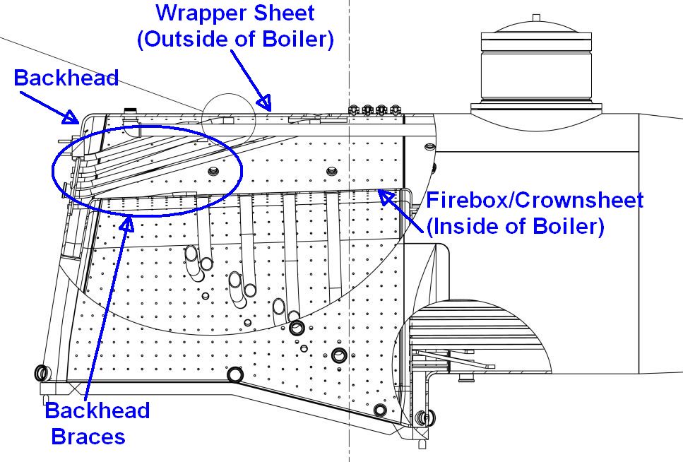
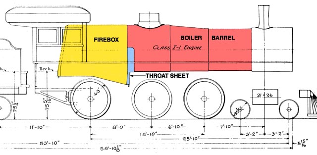
This drawing of an Omaha Road Class I-1 boiler, a sister engine to the R-1 class #1385, identifies the location of the firebox, throat sheet and boiler barrel.
The backhead forms the rear end of the firebox and is located inside the cab. The fireman shovels coal into the firebox via a small door which will be cut into the backhead.
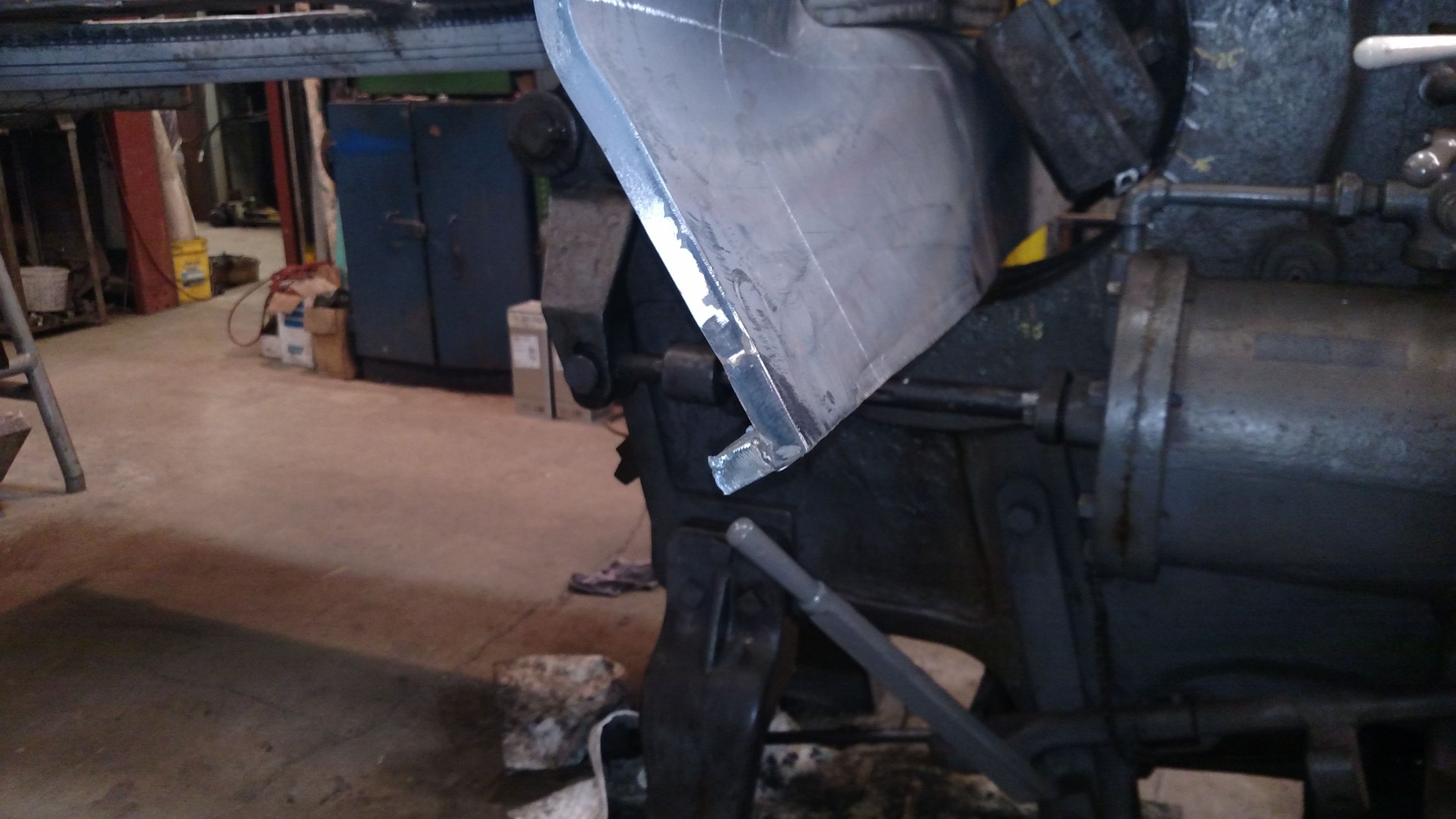
The already flanged (curved) sheet is the C&NW 1385’s new backhead. The backhead forms the end of the firebox inside the cab. Gary Bensman photo.
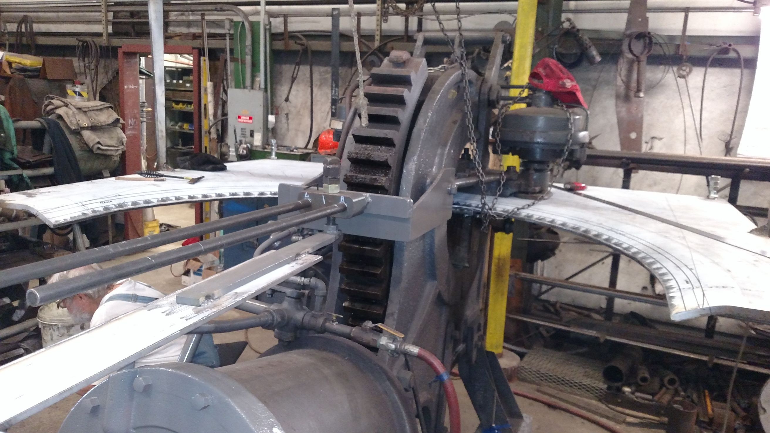
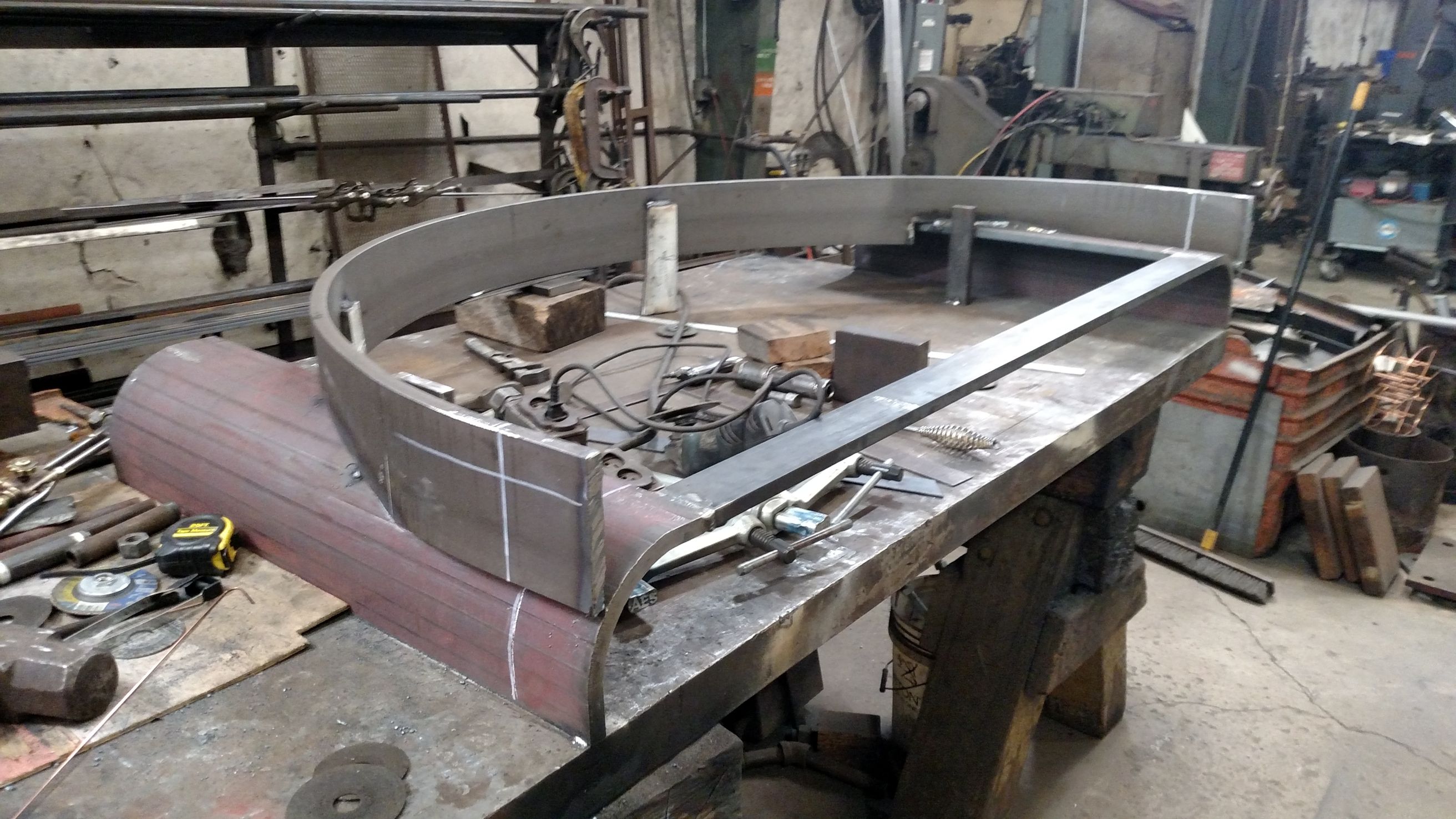
The throat sheet serves to connect the round boiler barrel with the firebox’s square-ish lower half. Such a transition requires the throat sheet to be a more complex shape. Where much of the bending of the steel sheets thus far could be accomplished via “cold flanging” by bending on a pneumatically-powered McCabe Flanger at room temperature, the throat sheet’s complex curves require a more hands-on approach. The “hot flanging” or “heat and beat” method involves heating the metal to make it more malleable and then using sledgehammers to pound it into the desired shape. The photo gallery below shows the throat sheet at various stages of progress.
The C&NW #1385’s new throat sheet as of the start of the day on April 4, 2017. The sheet is being bent or “flanged” on the McCabe Flanger. Gary Bensman photo.
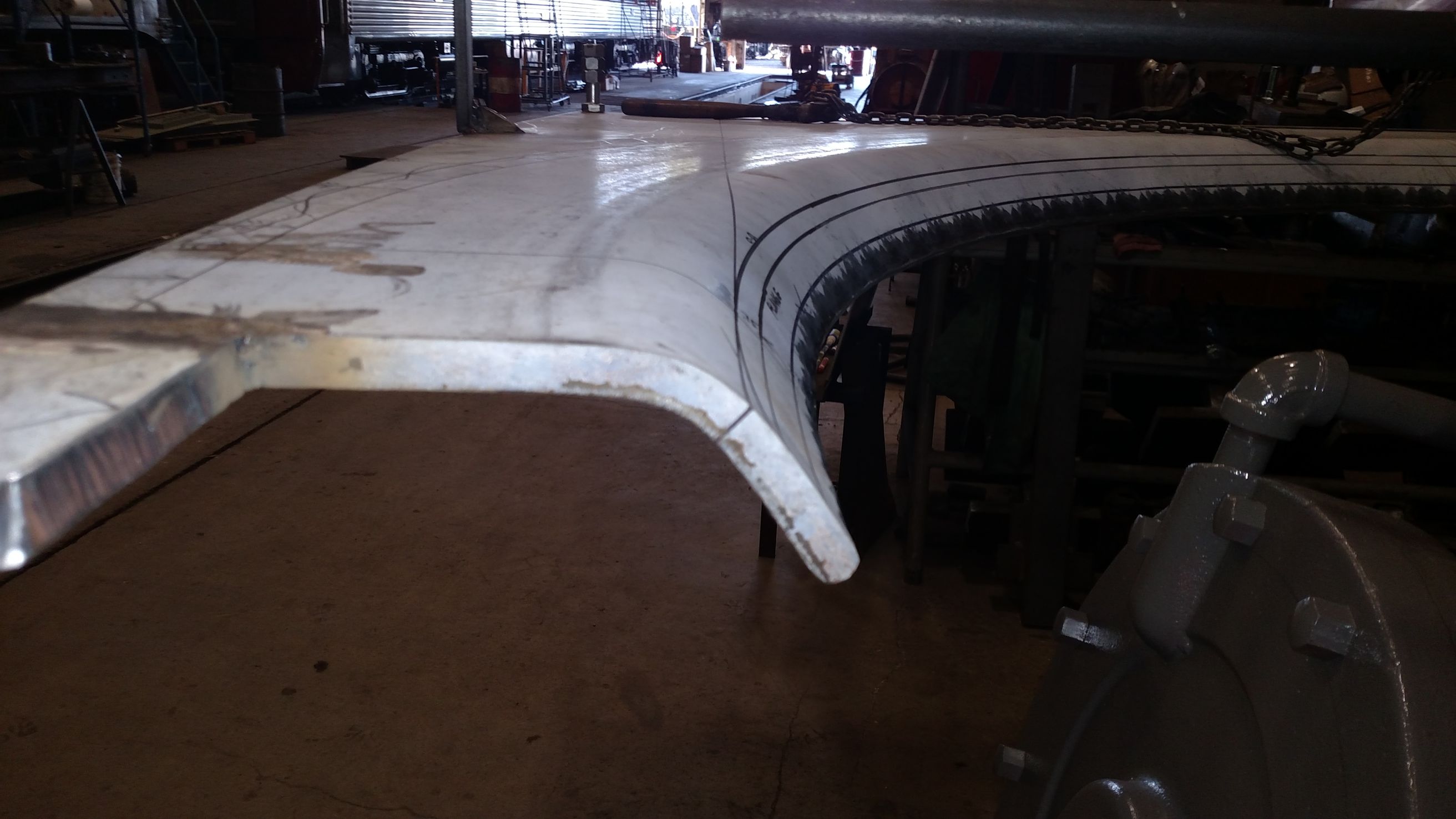
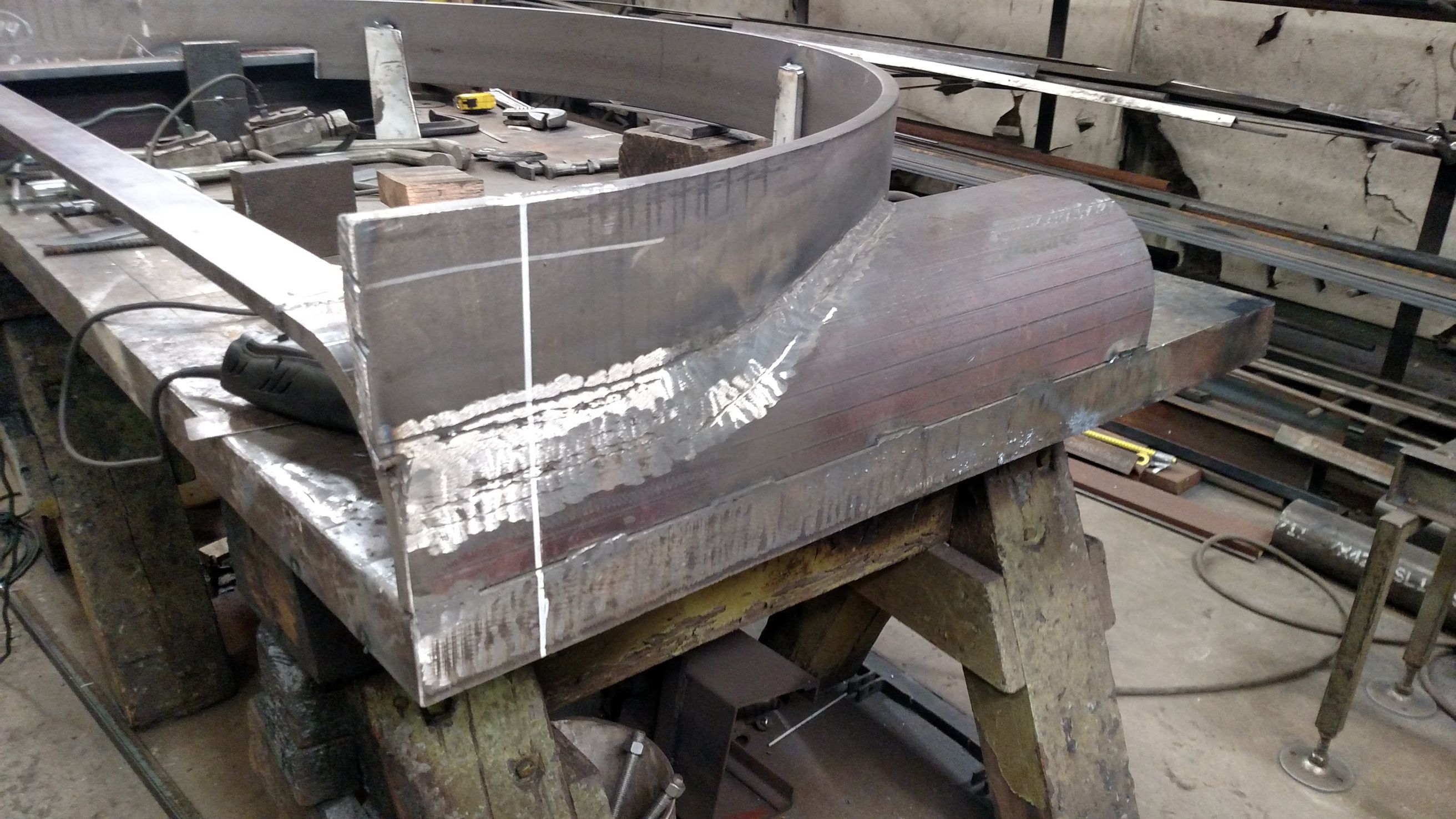
By the end of the day April 4th the throat sheet had been flanged to 65 degrees. Gary Bensman photo.
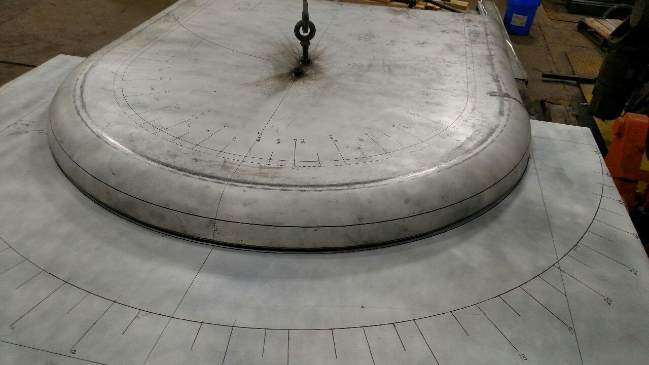
An underside view of the throat sheet after flanging to 65 degrees. Gary Bensman photo.
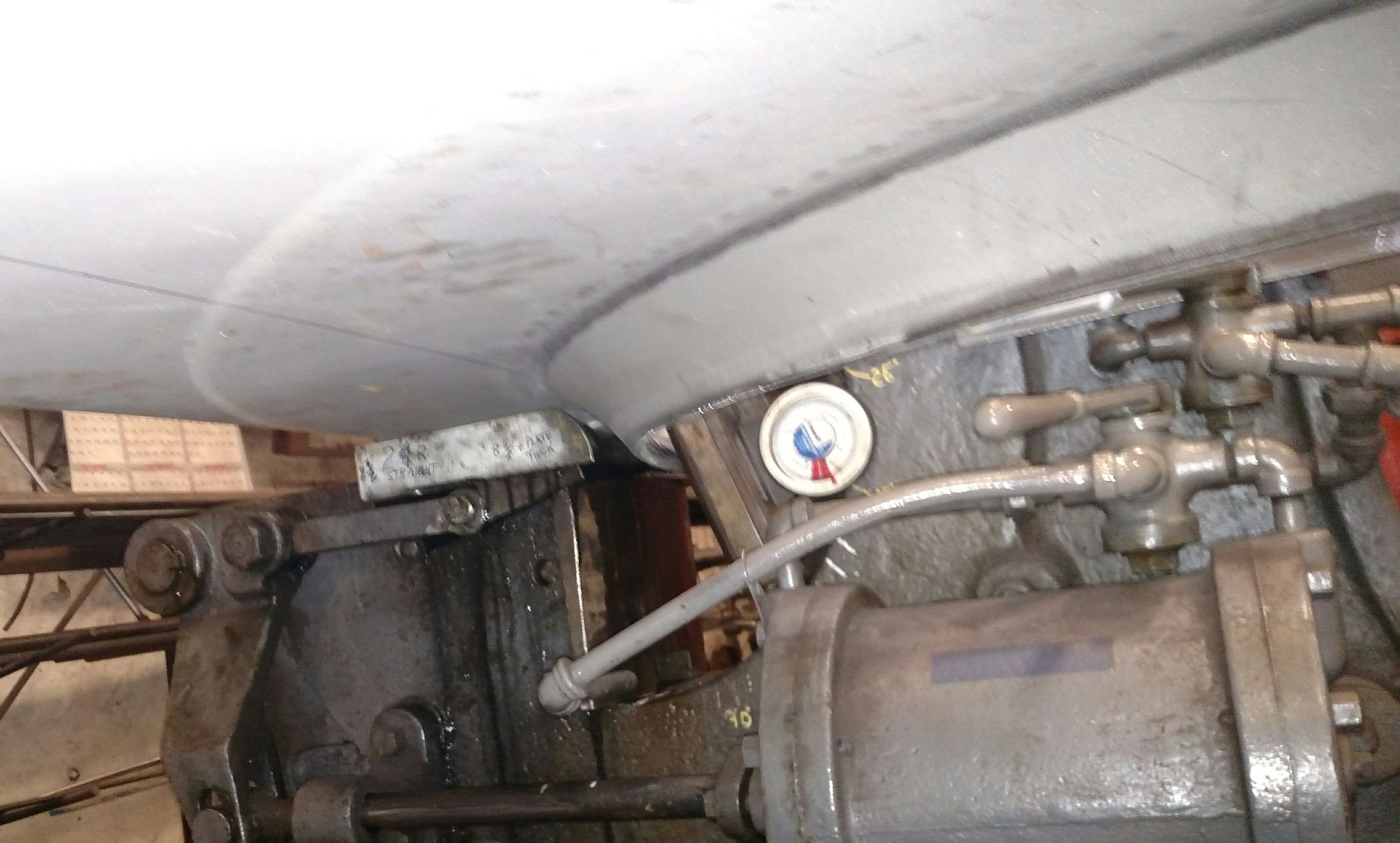
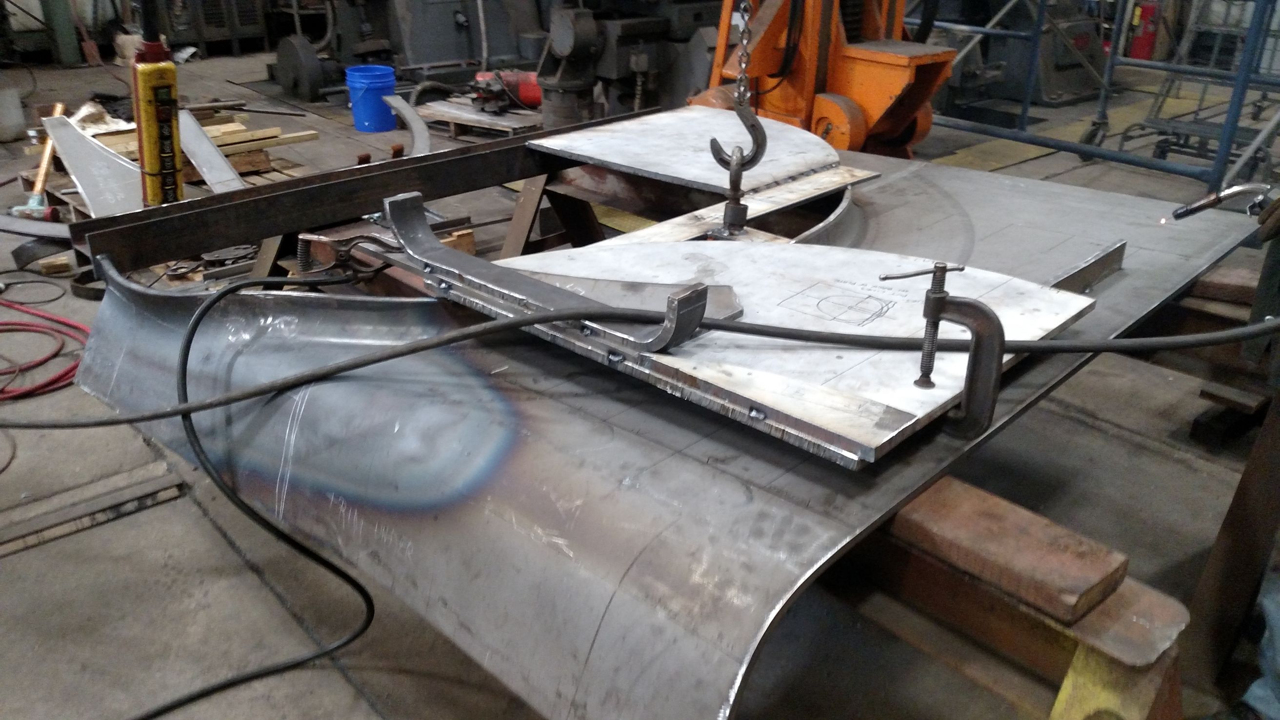
On April 5, the throat sheet was flanged the rest of the way from 65 degrees to 90 degrees. Gary Bensman photo.
By the end of the day April 5, the throat sheet belly flange was at 90 degrees at a 74″ inside diameter and work would resume the next day flanging the outside straight sections to a 75-1/2″ outside dimension. Gary Bensman photo.
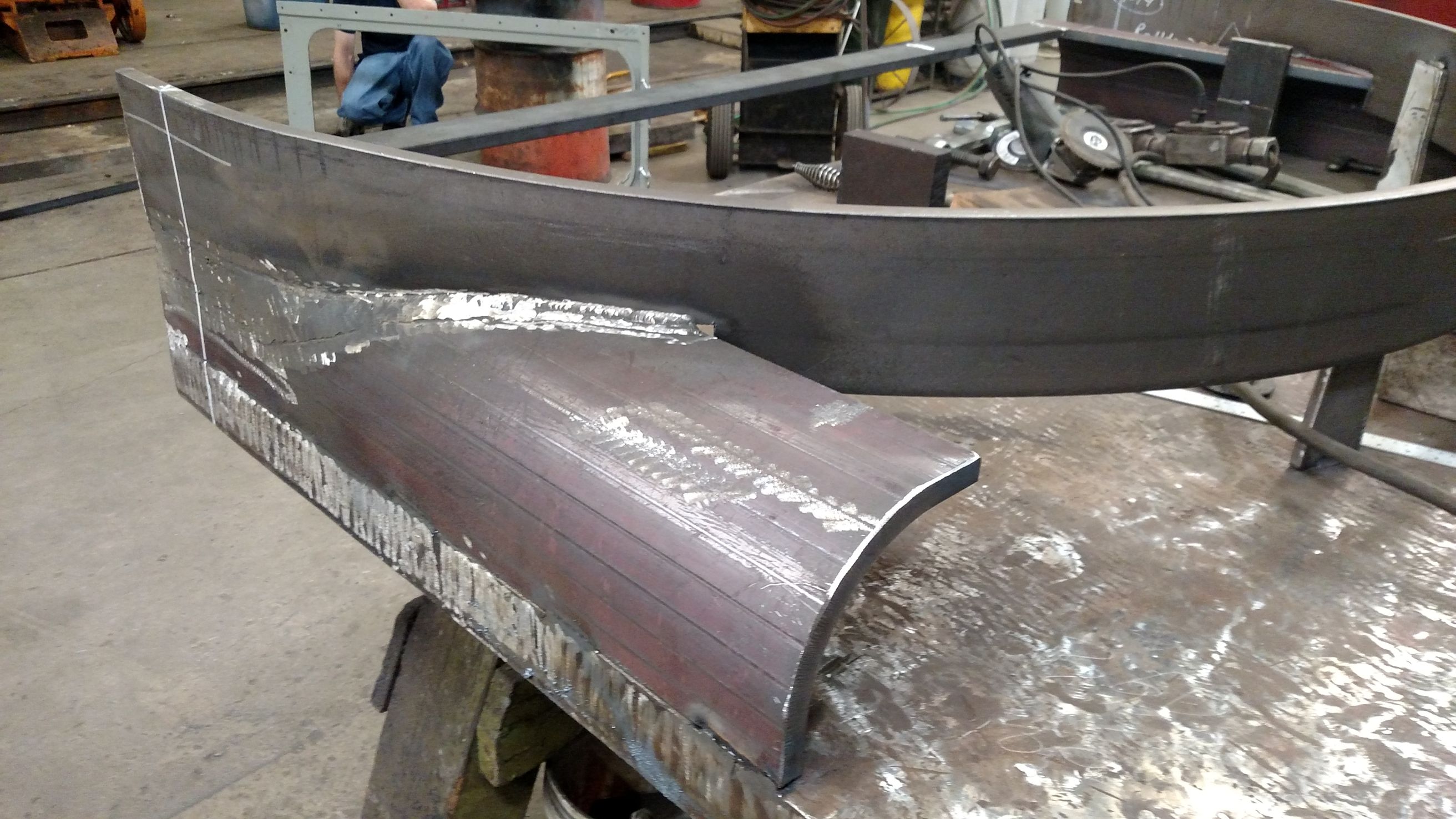
Forming the throat sheet’s “ears” could not be accomplished on the McCabe Flanger alone. Instead the “heat and beat” method was employeed. This form was fabricated to allow precision flanging using that method. Gary Bensman photo.
Additional view of the form fabricated to assist with the “heat and beat” flanging of the throat sheet. Gary Bensman photo.
Additional view of the form fabricated to assist with the “heat and beat” flanging of the throat sheet. Gary Bensman photo.
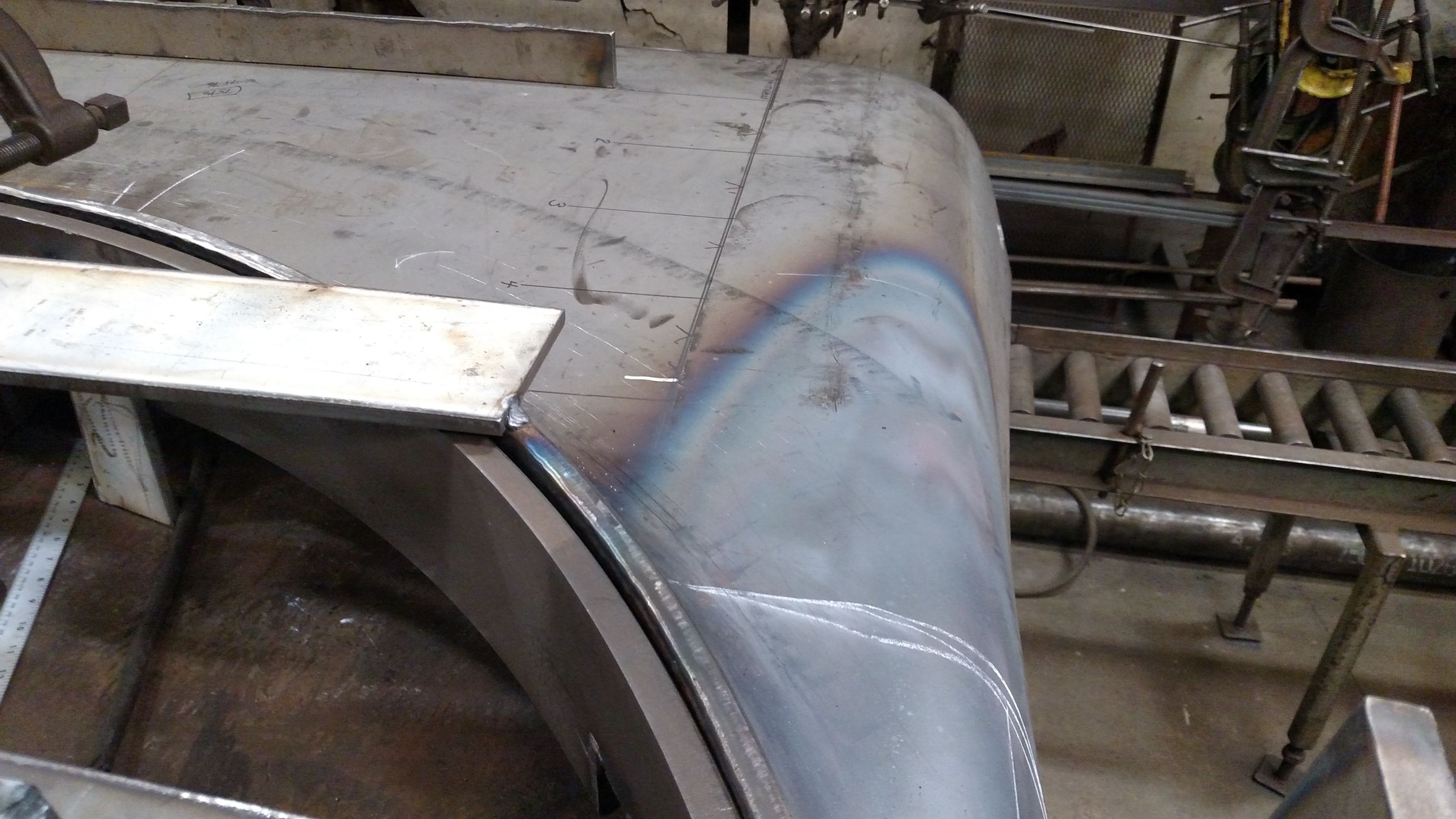
The change in color shows where heat was applied to allow the throat sheet sides to be hammered down to match the form. April 13, 2017. Gary Bensman photo.
Another view of the throat sheet side during flanging. April 13, 2017. Gary Bensman photo.
Flanging of the throat sheet sides could resume on the McCabe Flanger after the “heat and beat” method was used in the area of the complex shape where the throat sheet side flange and belly flange near one another. April 13, 2017. Gary Bensman photo.