Mid-Continent Railway MuseumPosted on by Jeffrey Lentz
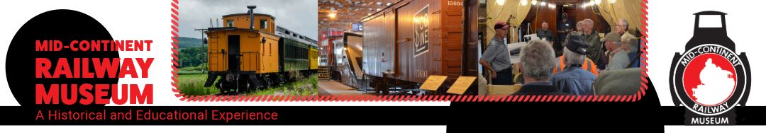
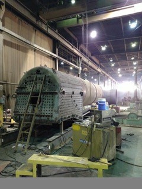
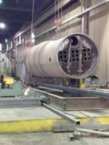
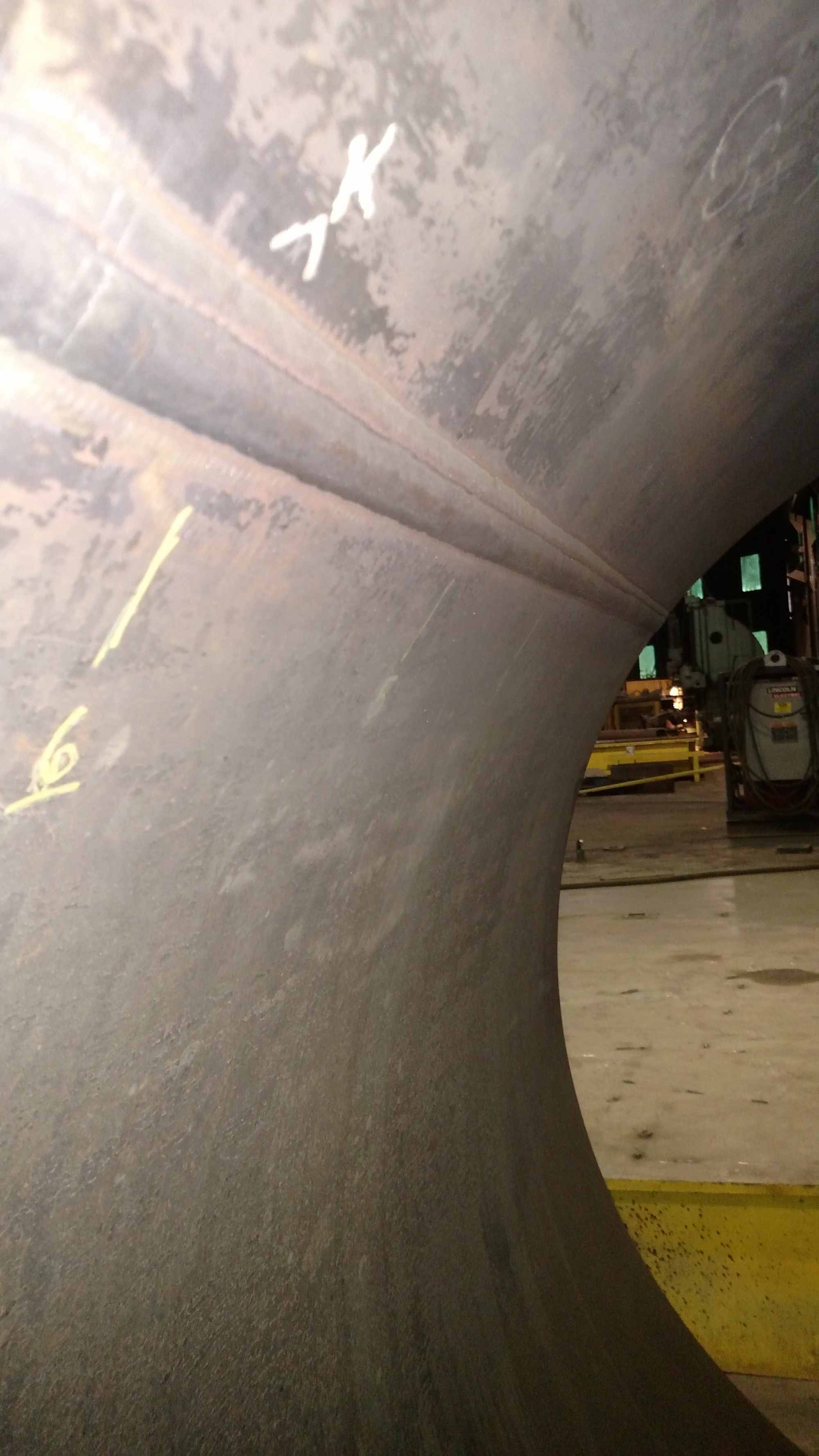
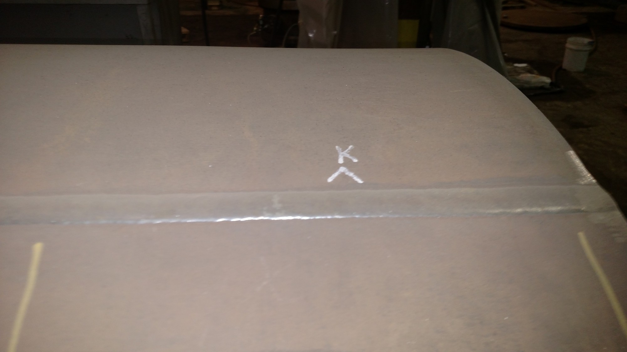
Continental Fabricators has supplied three new photos showing the current state of progress on Chicago & North Western #1385’s new boiler construction.
C&NW 1385’s new boiler firebox end. Oct. 31, 2018.
Mid-Continent Railway MuseumPosted on by Jeffrey Lentz
The Flannery Bolt Company is long gone but their products live on as their staybolt and staybolt accessories are reproduced today for projects like the Mid-Continent’s Chicago & North Western No. 1385. In the steam era staybolt production and replacement were a regular occurrence and such parts were readily available in large quantities. Even in 2018 there are at least two shops readily producing them as a specialty item, but for the 1385 project Mid-Continent has opted to keep it local, producing them in-house at SPEC Machine where the bulk of the locomotive’s overhaul and assembly is taking place.
1385 project volunteer Pete Deets explains, “We decided to have Steve Roudebush [owner of SPEC Machine] make them as the best way to control the cost and delivery schedule.” He adds, “The bolts to go with the sleeves and caps are on the way… there are 72 flexible staybolts on the 1385 but there are also a few hundred rigid stays that will go into the boiler.”
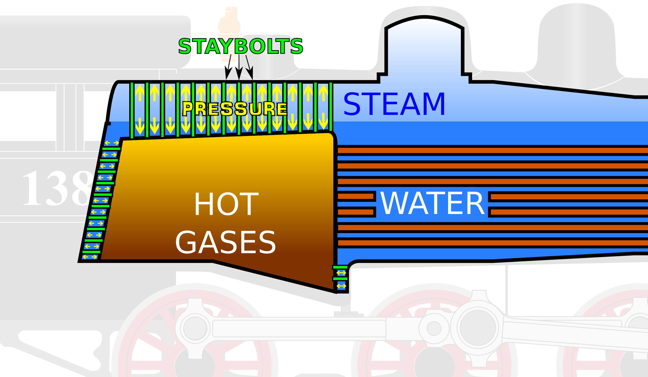
The majority of the boiler is cylindrical, a naturally strong shape, but there are also some flat and irregular surfaces within the boiler too, especially around the firebox. With the intense pressures up to 250 psi inside 1385’s boiler, these surfaces would weaken, bow, and eventually fail without staybolts to support them.
The flexability afforded by a flexible staybolt is critical to maintaining the boiler’s strength while still allowing for the expansion and contraction that occurs as temperatures change from one extreme to another within the boiler. Deets explains:
A flexible staybolt has a ball shape on one end and is threaded on the other. The ball end fits into and will be held by the cup shape of the inside of the sleeve. The sleeve will be welded on the outside or wrapper sheet of the boiler above the firebox. The bolt is then dropped into the sleeve and the threaded end is screwed into a threaded hole in the firebox. The bolt is hammered or “upset” to cause it to swell into the threads and form a steam tight seal and a copper gasket is applied with the cap to seal the sleeve end. The ball end of the bolt can actually swivel in the cup shape of the cap and it allows the firebox to move in relation to the wrapper sheet of the boiler as the engine goes down the road. [Locomotive designers] found that allowing that slight bit of movement was better overall for the boiler than trying to hold every bit very stiff and rigid. If things were too rigid the boiler would break the staybolts anyway. It was also noted there were fairly specific areas of a boiler that were prone to breaking stays so the Railroad Master Mechanics Committee came out with recommended patterns of placement for the flexi’s to alleviate or at least minimize the breakage.
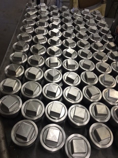
New flexible stay caps and sleeves were fabricated in January 2018 by SPEC Machine for C&NW 1385. The accompanying bolts are currently in production. Photo courtesy SPEC Machine.
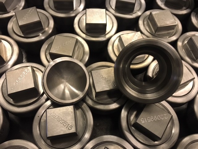
Flexible staybolt cap and sleeve detail. Photo courtesy SPEC Machine.
The photos of the staybolt caps reveal a series of numbers stamped on each one. The number represents the part’s “heat number.” That is a jargon from the steel industry as they refer to every batch of iron or steel (or any metal) that comes out of a furnace as a “heat.”
Deets elaborates on the importance of heat numbers:
That number is vital because every piece of metal that goes into the pressure retaining portion of the boiler must meet very specific requirements of physical strength, mechanical properties and chemical properties and we have to be able to prove the materials we use meet those specs. Every batch of steel made is tested for chemistry and physical properties and is assigned a unique number. The records of those batches made for specific applications such as boiler plate follow the steel through the finishing process of the mill and each piece is marked with the heat number and other information. Those records are the certification that this particular batch or heat number meets this specific set of requirements and we must get a copy of and keep on file the material certifications or “certs” for short. That heat number represents the “pedigree” of each of those parts.
The below YouTube video produced by Wasatch Railroad Contractors while working on a different locomotive restoration provides a good illustration and explanation of how flexible staybolts work.
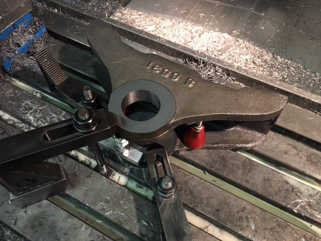
Last but not least, SPEC Machine has also been busy finishing up more work on 1385’s brake equipment. Brand new brake heads were cast last summer (see post from Sept. 1, 2017) and are now being machined in preparation for installation.
One of the newly cast brake heads is machined to specification. Each brake head supports one of 1385’s brake shoes.
Mid-Continent Railway MuseumPosted on by Jeffrey Lentz
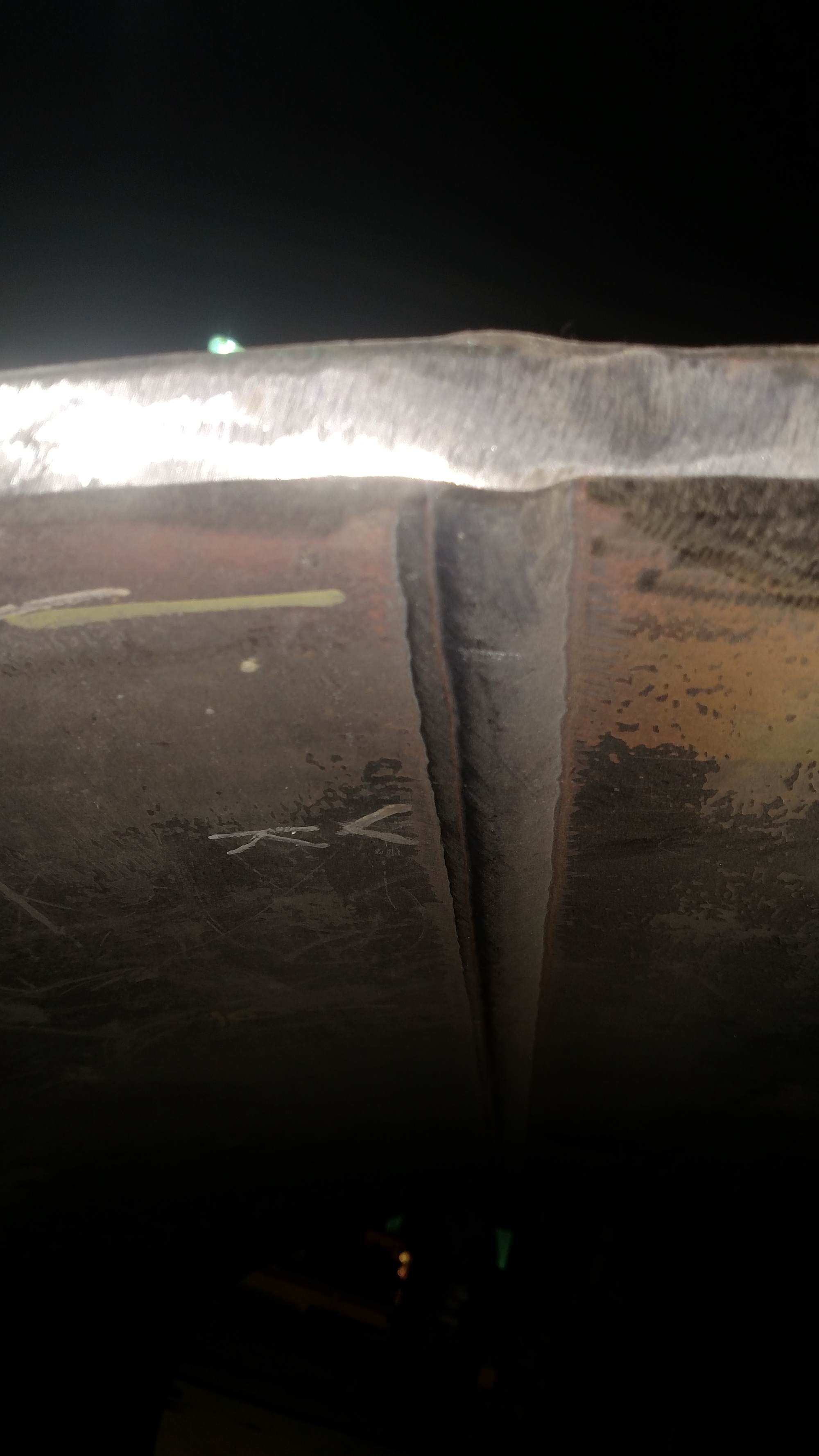
The assembly of C&NW 1385’s boiler began in earnest late last week at Continental Fabricators in St. Louis. Here are the latest photos from the shop floor, courtesy of Gary Bensman.
C&NW 1385’s front flue sheet. Jan. 21, 2018. Gary Bensman photo.
C&NW 1385’s backhead sheet. Jan. 21, 2018. Gary Bensman photo.
Mid-Continent Railway MuseumPosted on by Jeffrey Lentz
Gary Bensman and his team continued work flanging various sheets for the C&NW 1385’s firebox during the first half of April. Recent tasks included work on the 1385’s throat sheet and backhead.
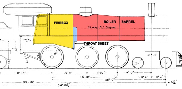
This drawing of an Omaha Road Class I-1 boiler, a sister engine to the R-1 class #1385, identifies the location of the firebox, throat sheet and boiler barrel.
The backhead forms the rear end of the firebox and is located inside the cab. The fireman shovels coal into the firebox via a small door which will be cut into the backhead.
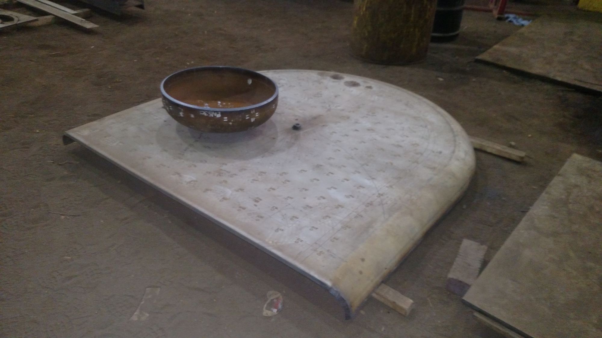
The already flanged (curved) sheet is the C&NW 1385’s new backhead. The backhead forms the end of the firebox inside the cab. Gary Bensman photo.
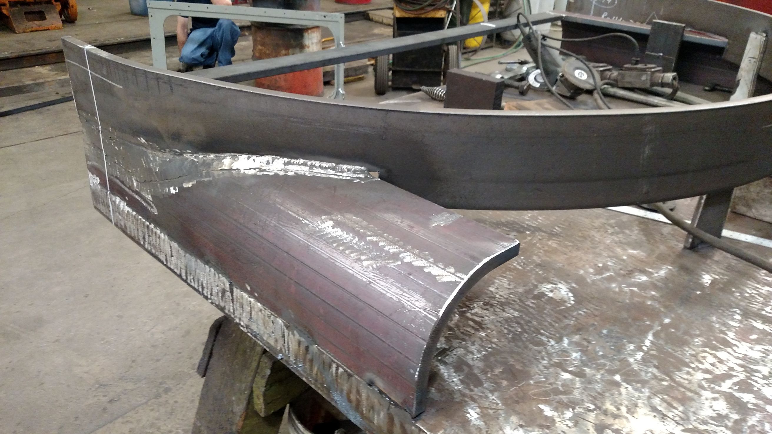
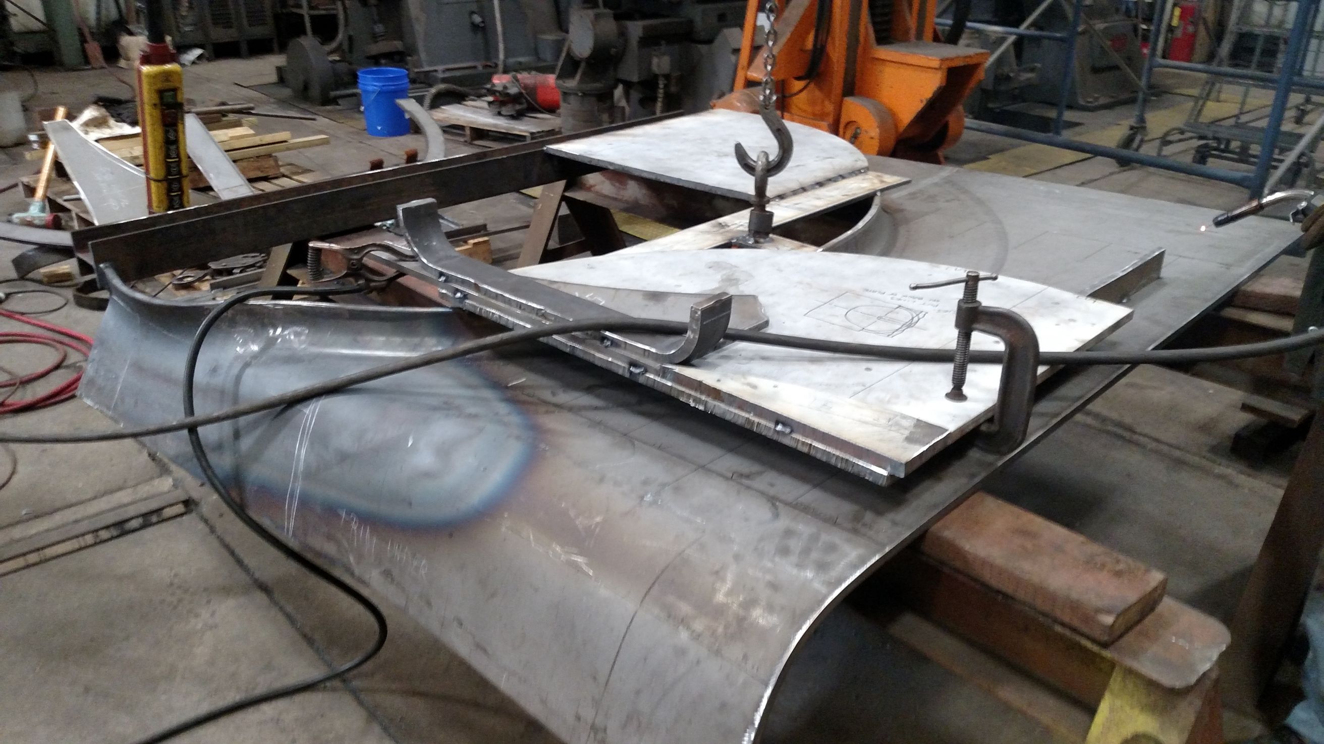
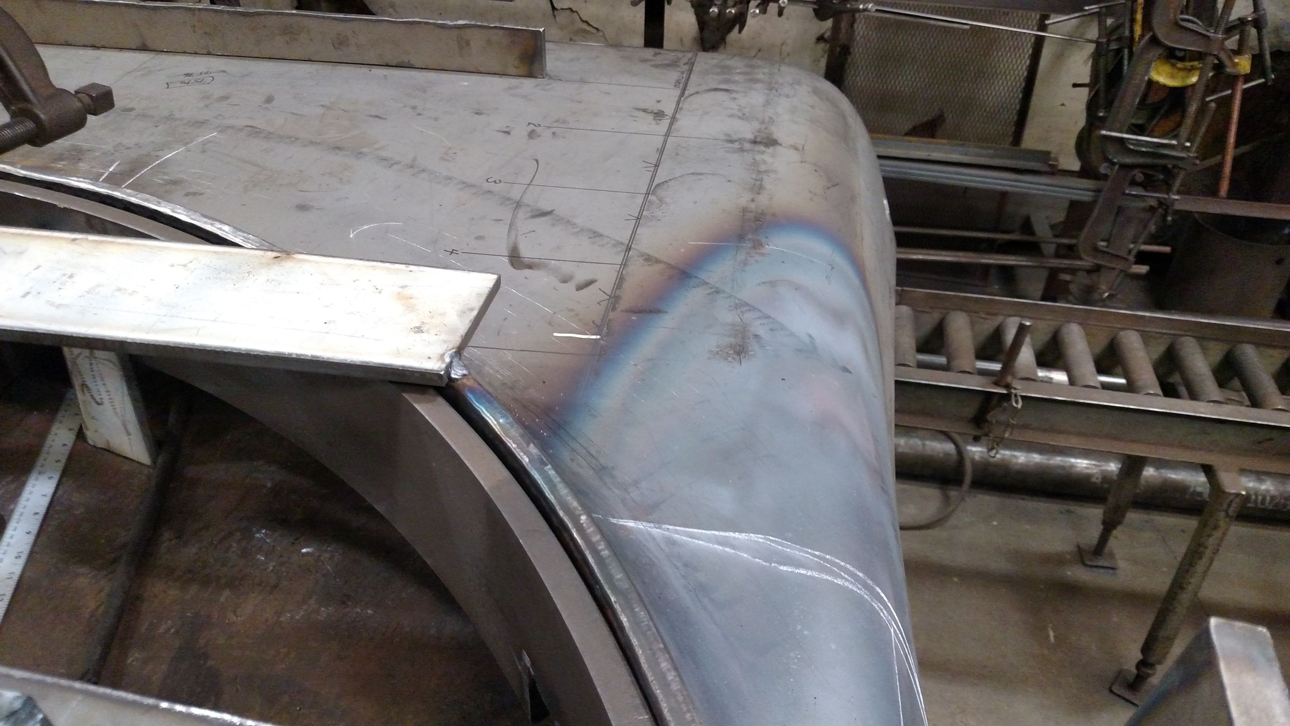
The throat sheet serves to connect the round boiler barrel with the firebox’s square-ish lower half. Such a transition requires the throat sheet to be a more complex shape. Where much of the bending of the steel sheets thus far could be accomplished via “cold flanging” by bending on a pneumatically-powered McCabe Flanger at room temperature, the throat sheet’s complex curves require a more hands-on approach. The “hot flanging” or “heat and beat” method involves heating the metal to make it more malleable and then using sledgehammers to pound it into the desired shape. The photo gallery below shows the throat sheet at various stages of progress.
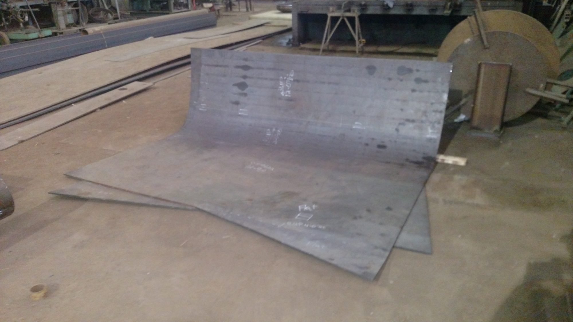
The C&NW #1385’s new throat sheet as of the start of the day on April 4, 2017. The sheet is being bent or “flanged” on the McCabe Flanger. Gary Bensman photo.
By the end of the day April 4th the throat sheet had been flanged to 65 degrees. Gary Bensman photo.
An underside view of the throat sheet after flanging to 65 degrees. Gary Bensman photo.
On April 5, the throat sheet was flanged the rest of the way from 65 degrees to 90 degrees. Gary Bensman photo.
By the end of the day April 5, the throat sheet belly flange was at 90 degrees at a 74″ inside diameter and work would resume the next day flanging the outside straight sections to a 75-1/2″ outside dimension. Gary Bensman photo.
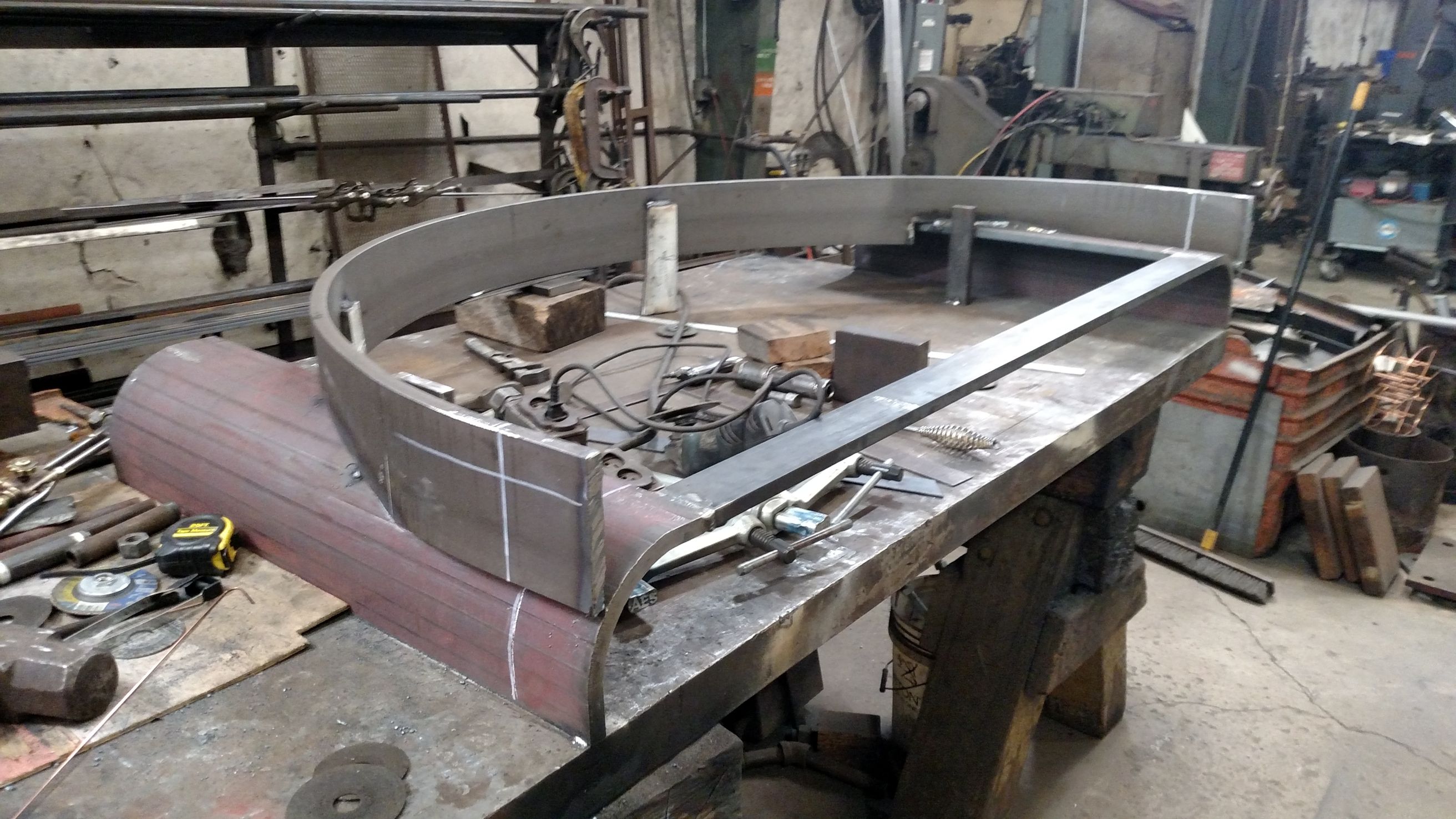
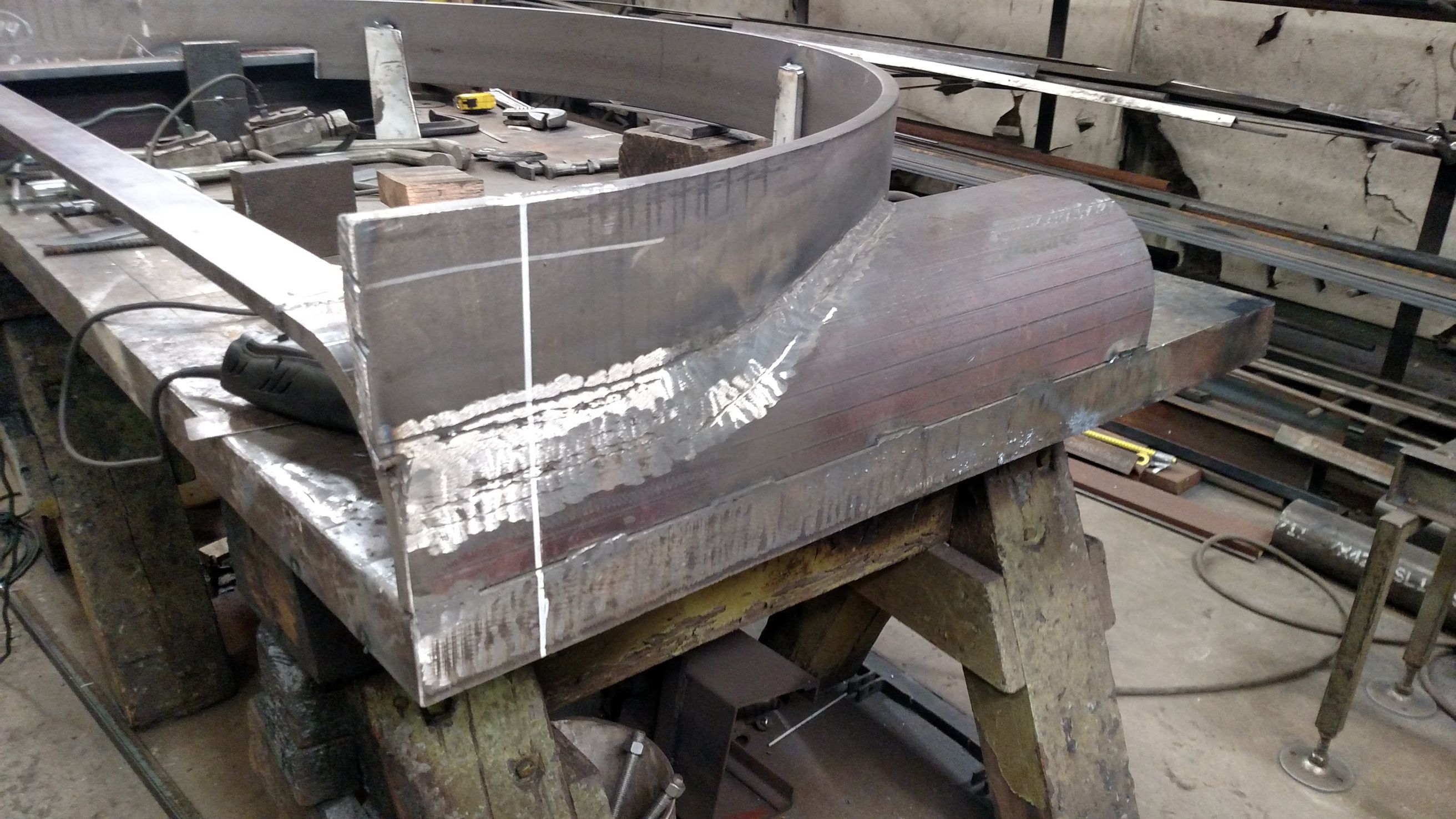
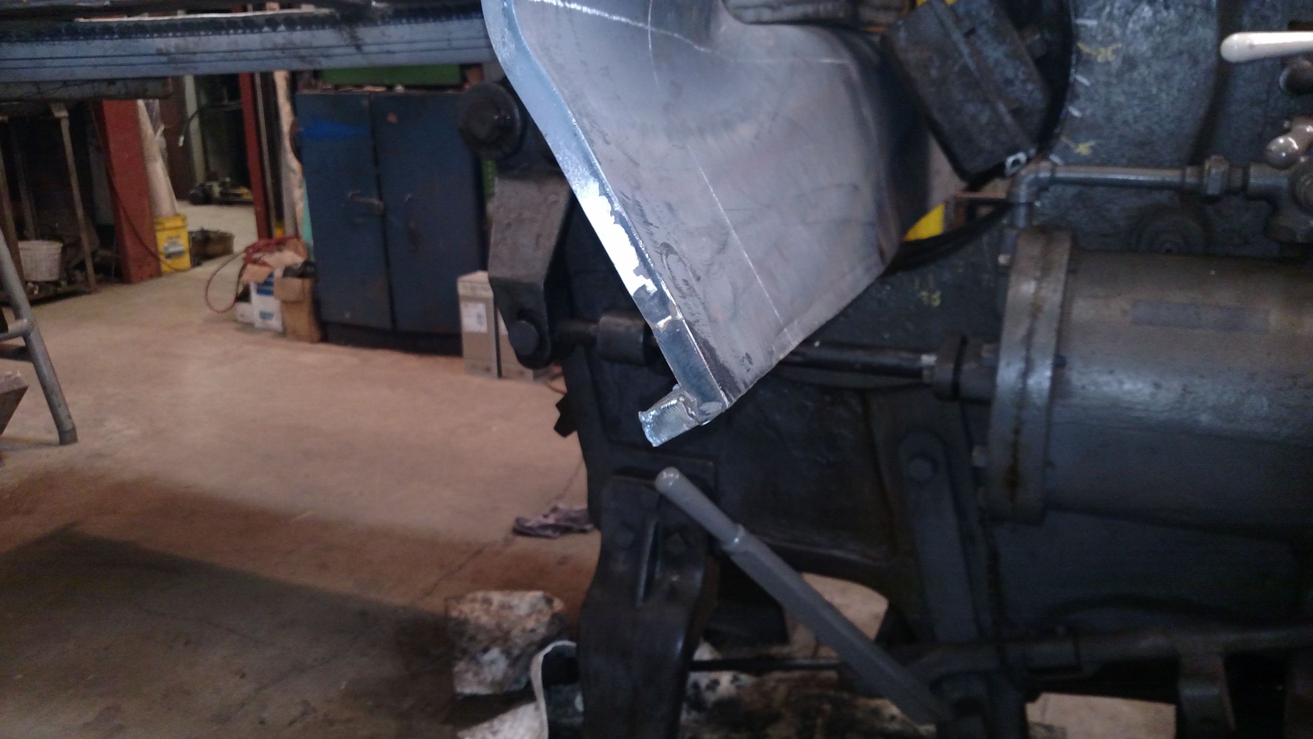
Forming the throat sheet’s “ears” could not be accomplished on the McCabe Flanger alone. Instead the “heat and beat” method was employeed. This form was fabricated to allow precision flanging using that method. Gary Bensman photo.
Additional view of the form fabricated to assist with the “heat and beat” flanging of the throat sheet. Gary Bensman photo.
Additional view of the form fabricated to assist with the “heat and beat” flanging of the throat sheet. Gary Bensman photo.
The change in color shows where heat was applied to allow the throat sheet sides to be hammered down to match the form. April 13, 2017. Gary Bensman photo.
Another view of the throat sheet side during flanging. April 13, 2017. Gary Bensman photo.
Flanging of the throat sheet sides could resume on the McCabe Flanger after the “heat and beat” method was used in the area of the complex shape where the throat sheet side flange and belly flange near one another. April 13, 2017. Gary Bensman photo.
Mid-Continent Railway MuseumPosted on by Jeffrey Lentz
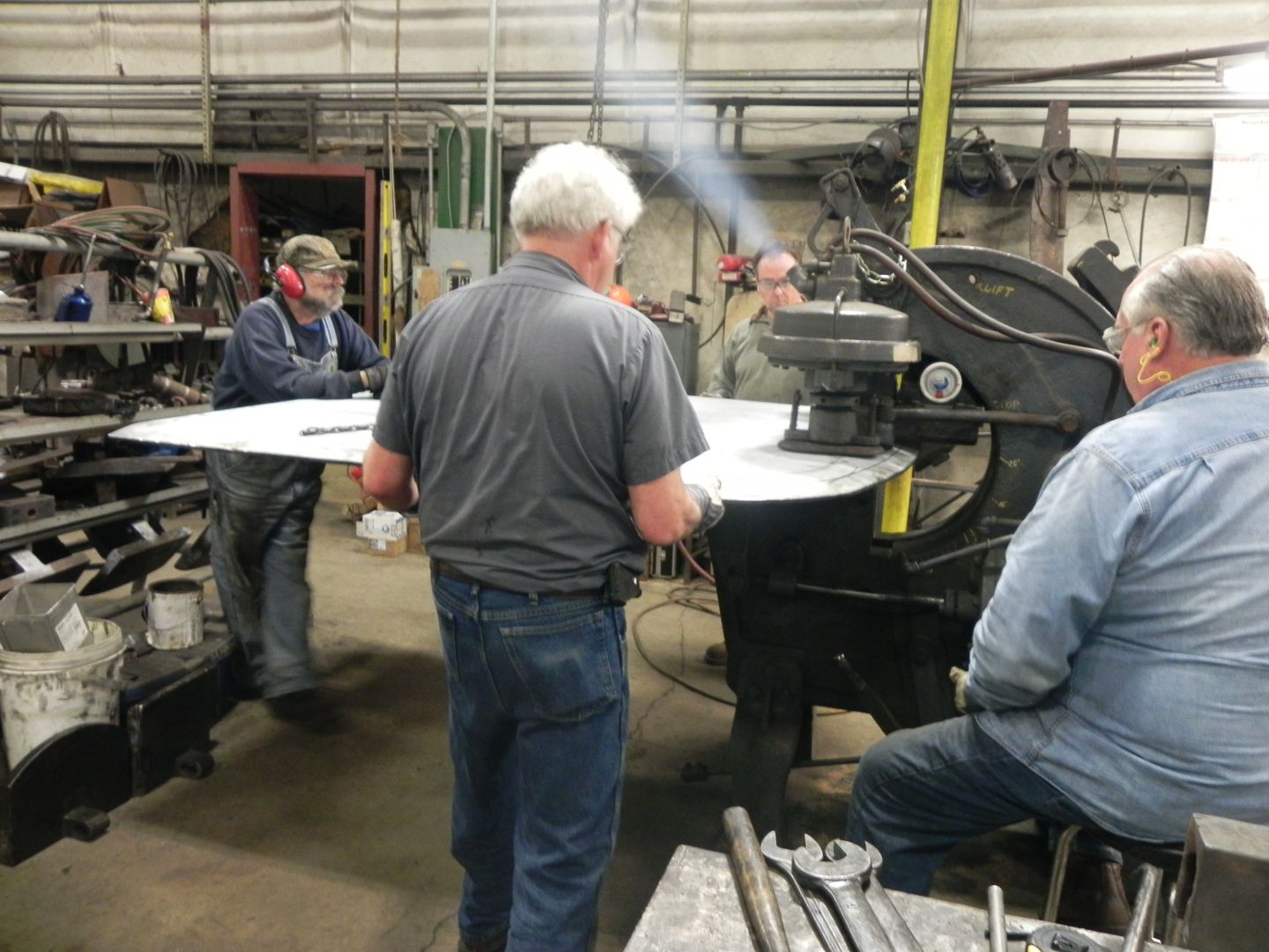
During the second week of March, SPEC Machine’s Steve Roudebush and Tyler Roudebush along with Brett Morley of Performance Engineering traveled to Tennessee Valley Railway Museum to meet with and assist Gary Bensman of Diversified Rail Services. Diversified Rail Services was contracted by Continental Fabricators to flange the four firebox sheets needed in building 1385’s new boiler.
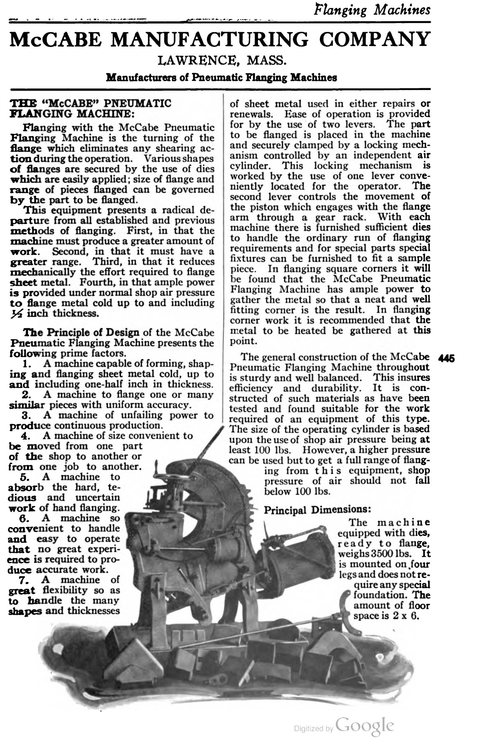
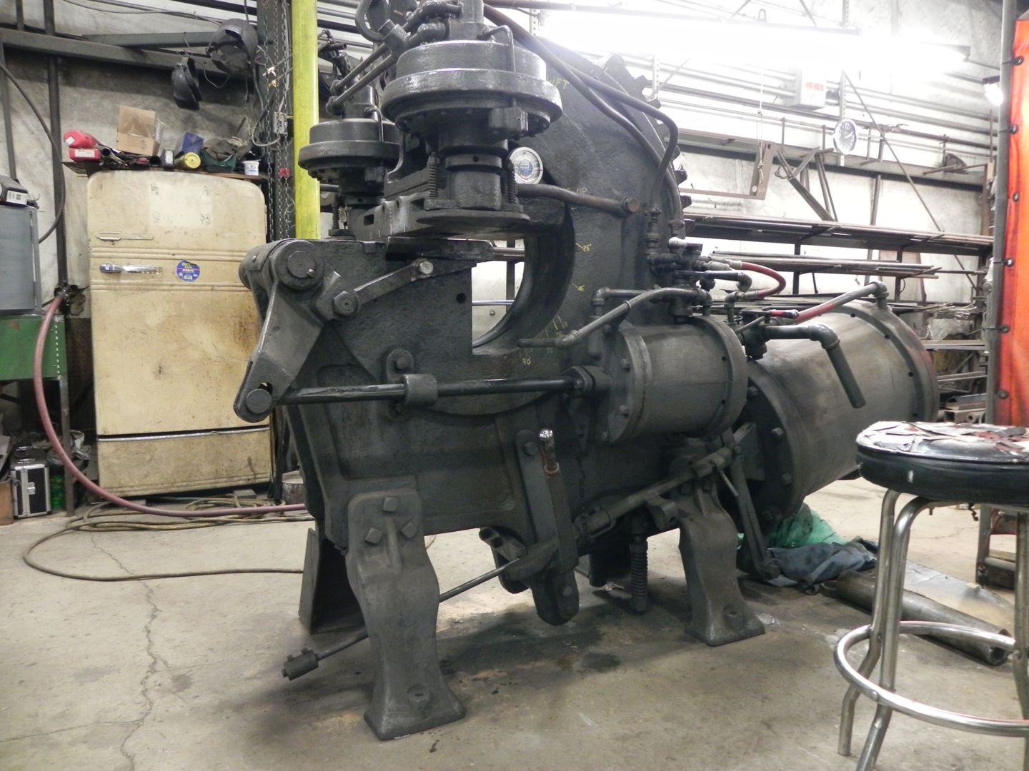
The McCabe Flanger in a 1921 American Society of Mechanical Engineers Catalogue and Directory.
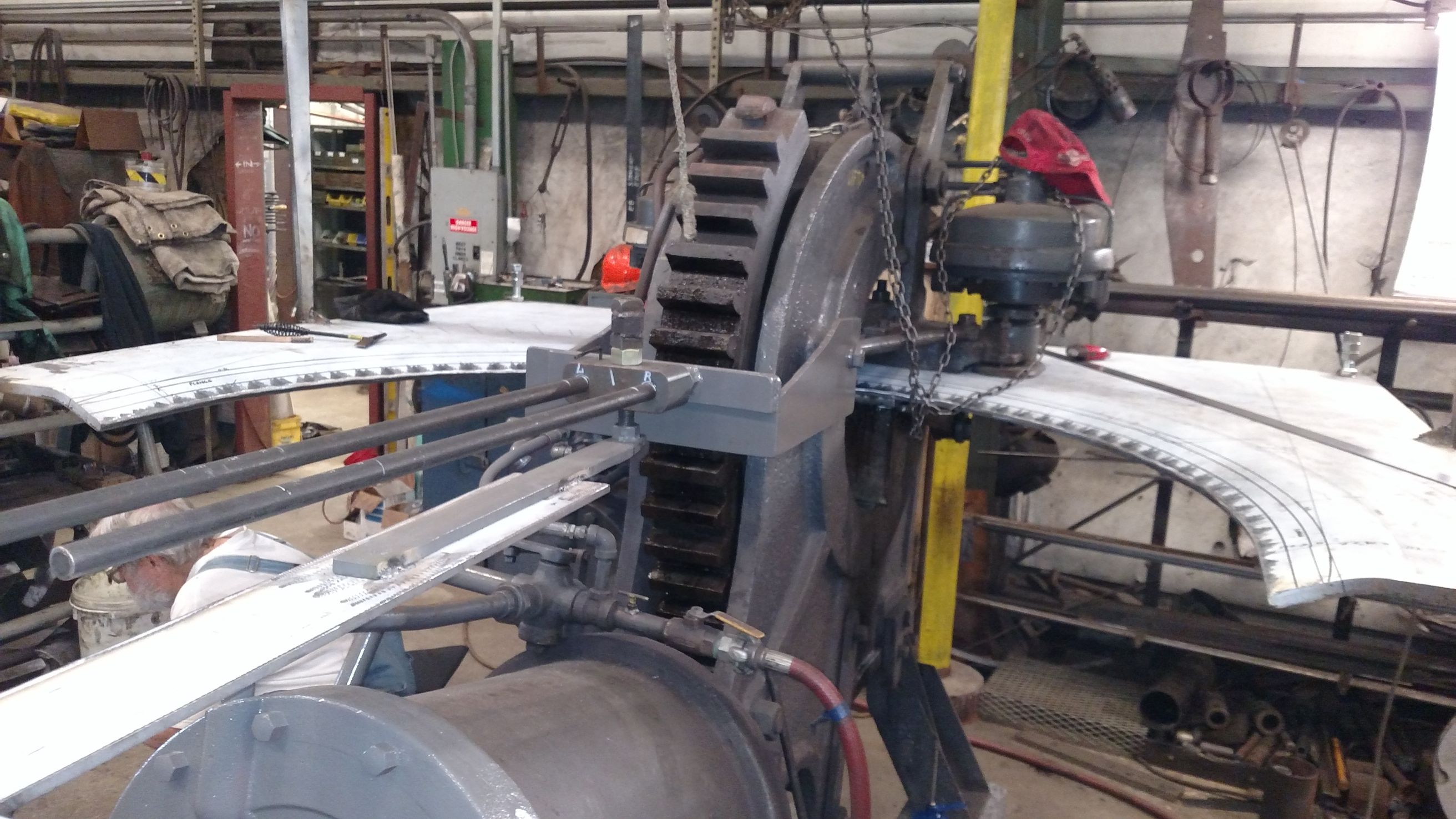
Flanging is a process to make a smooth bend in steel forms while the steel is cold. Flanging can also be done while the steel is hot but it adds more time, work and requires more people. The choice of whether to use hot or cold flanging is made largely on the shape being bent and where on the sheet of steel the bend needs to be made.
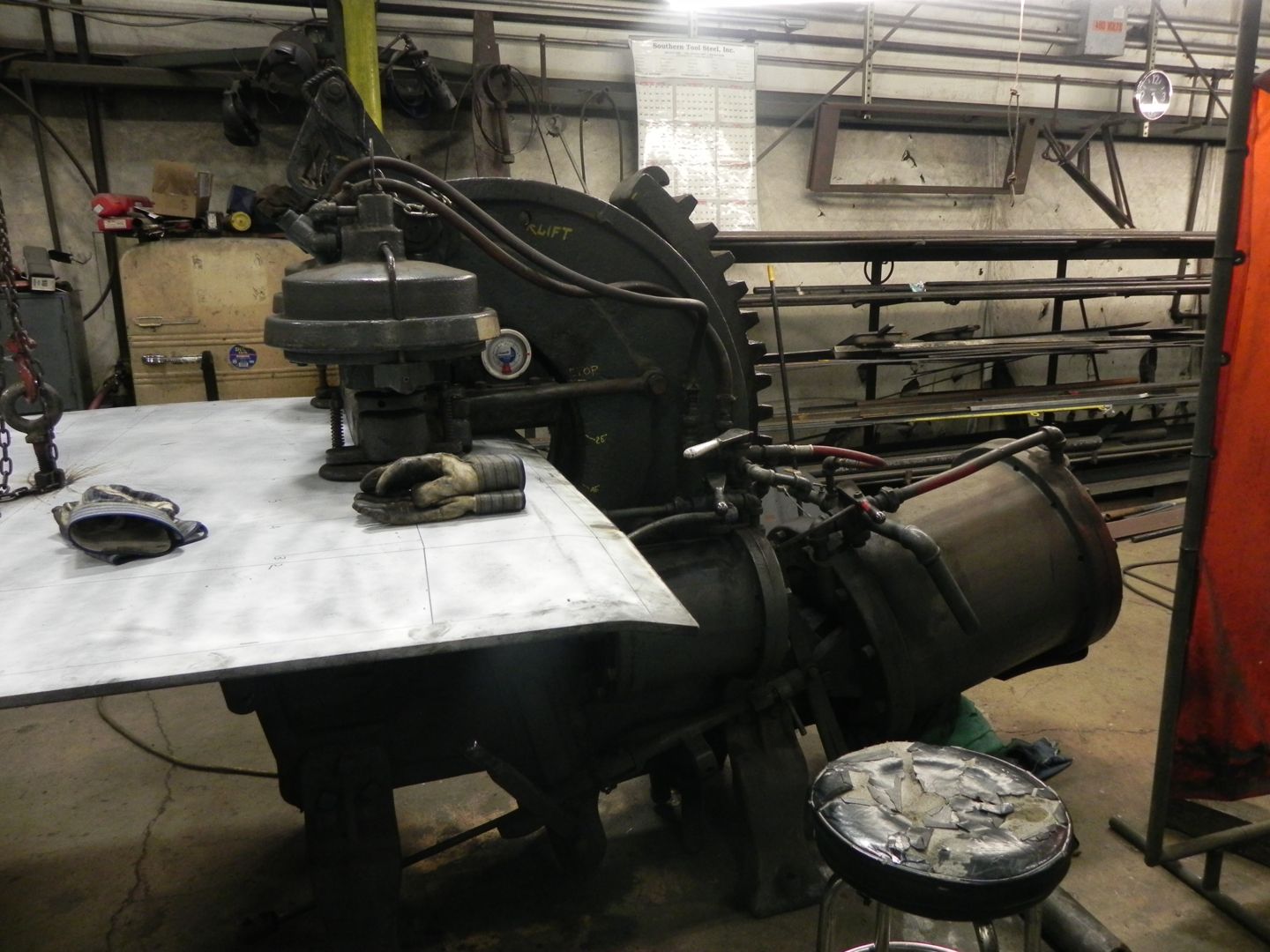
The machine seen in use here is a McCabe Flanger, a steam-era machine which uses pneumatic pressure for power. The bends are made a little at a time to prevent creating a wrinkle in the sheet.
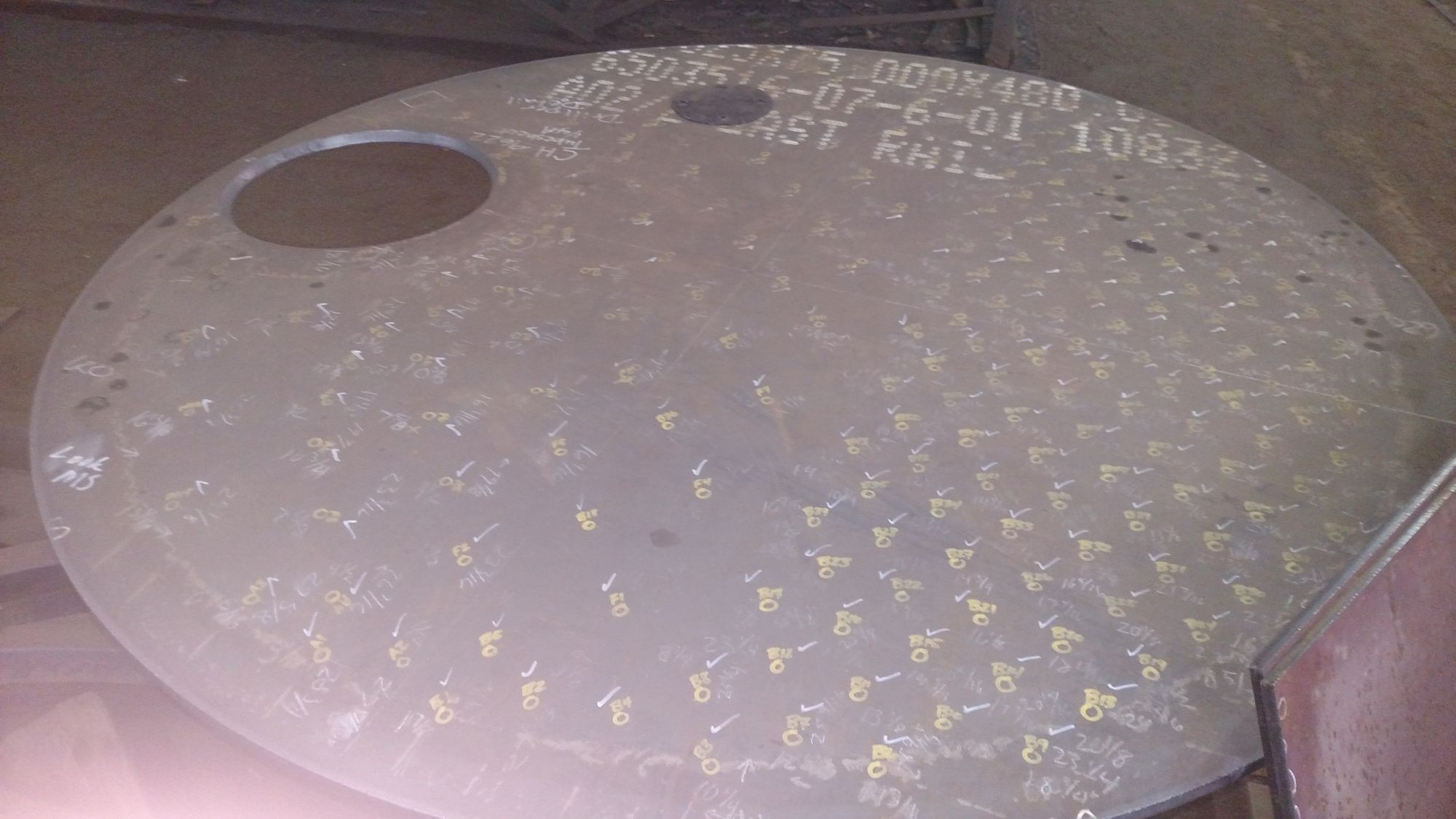
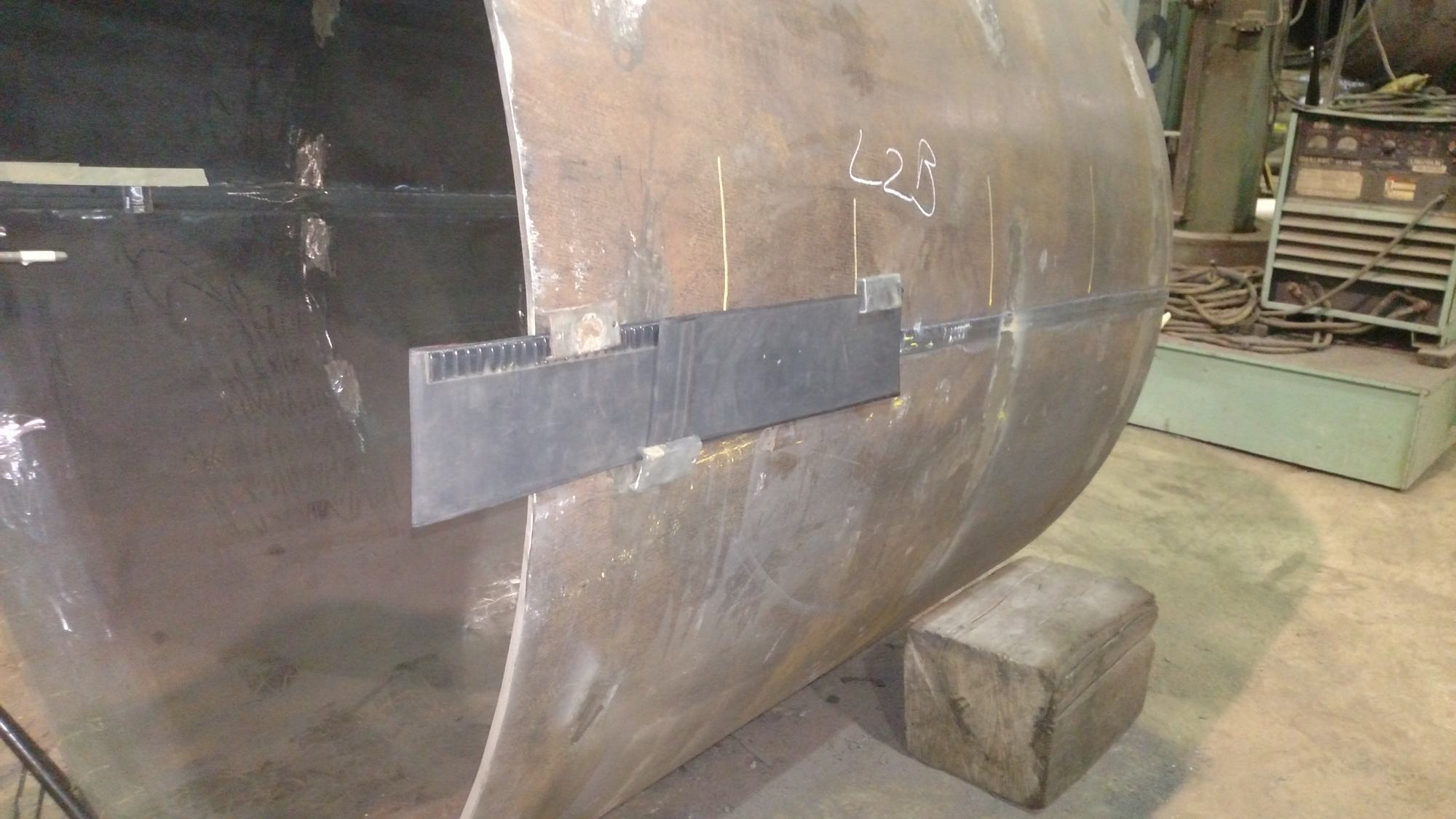
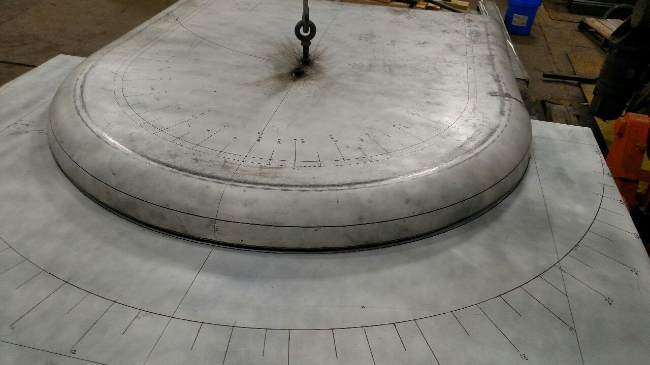
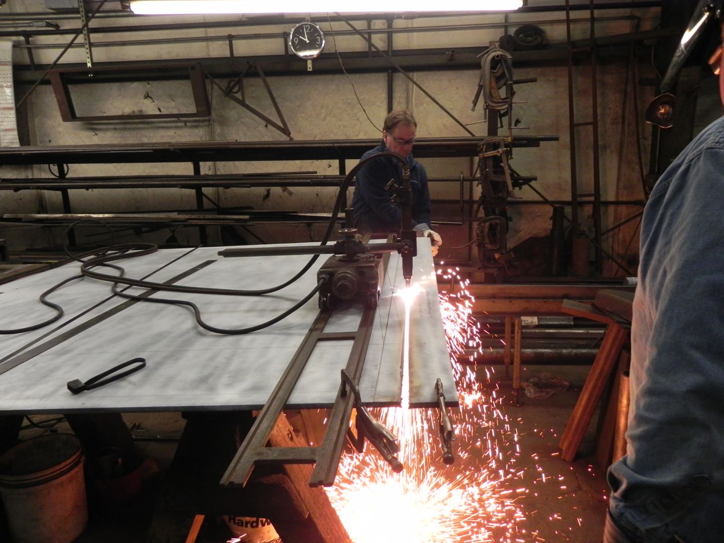
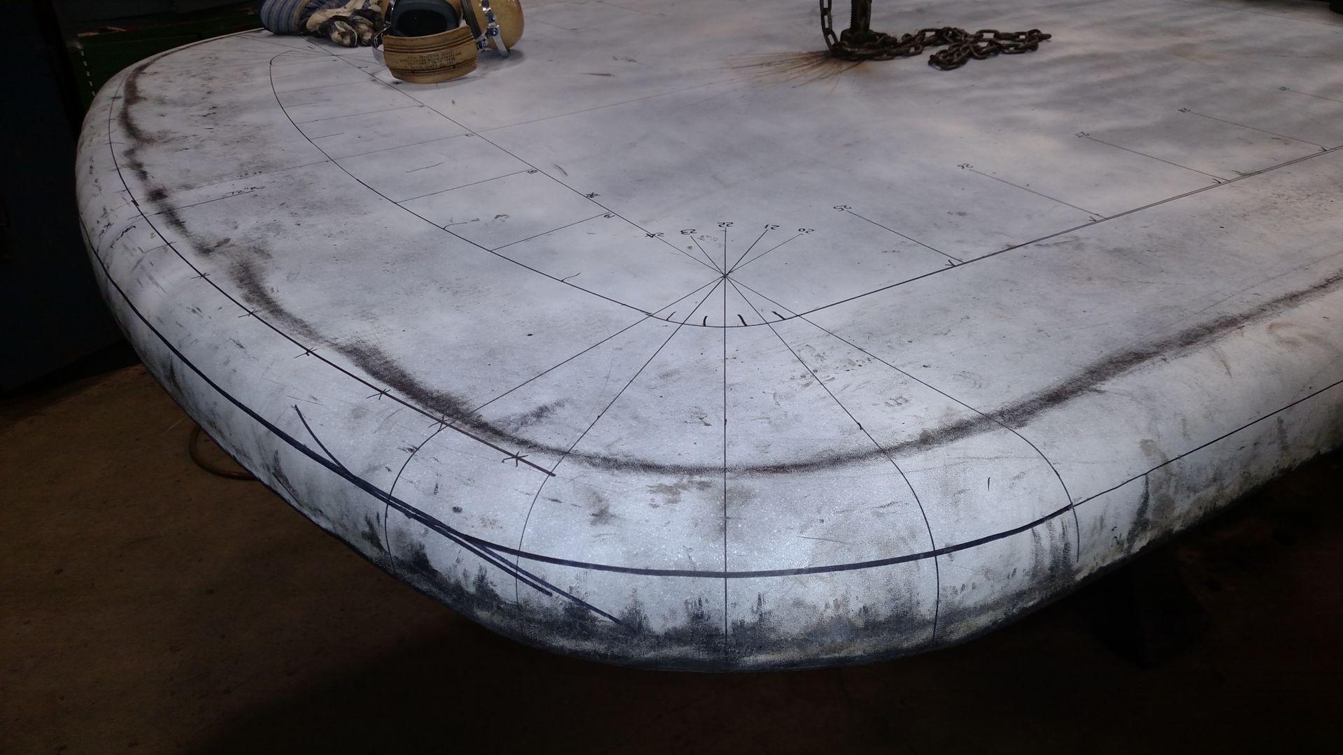
The accompanying photos show the the aforementioned persons along with formation of the 1385’s rear tube sheet. The tube sheet forms the front of the firebox, meaning one side will be exposed to intense fire and combustion gases while the other side will hold back a wall of water. Before being installed, the rear tube sheet will have holes drilled for and support nearly 200 2-inch fire tubes and 24 superheater flues. The tubes and flues go through the water space of the boiler to conduct the combustion gases from the firebox to the smokebox at the front of the locomotive and allow the water and steam time to absorb more heat from those gases. The tubes and flues also serve to help support the tube sheet. Since the sheet is a large, flat surface, steam pressure is constantly pushing on it, trying to bow the sheet, but the tubes and flues mechanically tie together the front and rear tube sheets, providing strength and holding the sheets flat.
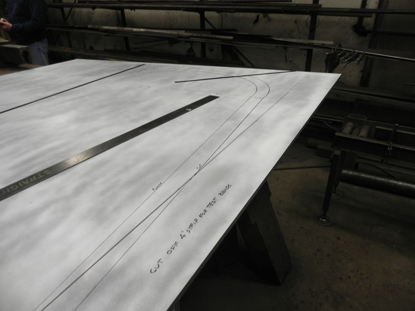
The metal sheet which will form the 1385’s rear tube sheet is carefully measured before any cutting or bending begins. Photo courtesy SPEC Machine.
Excess material is removed from the rear tube sheet using a torch track. The self-propelled cutting torch gives a better cut over a long distance than can be achieved by hand. Photo courtesy SPEC Machine.
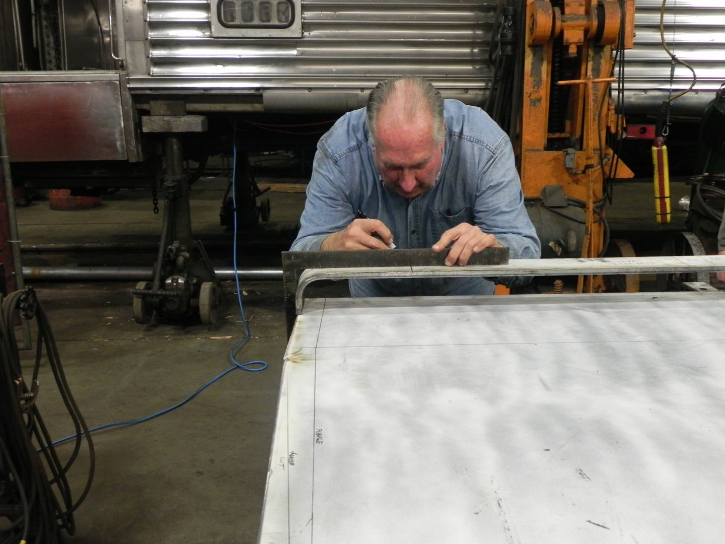
Gary Bensman carefully marks the locations and degree of the bends to be made. Photo courtesy SPEC Machine.
The McCabe Flanger machine at Tennessee Valley Railway Museum’s shop. Photo courtesy SPEC Machine.
The rear tube sheet is marked up and ready for the flanger. Photo courtesy SPEC Machine.
Crew members move the sheet into position. Photo courtesy SPEC Machine.
Steam veterans Gary Bensman, operating the McCabe Flanger, and Al “Uncle Al” Phillips (left), are assisted by 1385 Team representatives Steve Roudebush and Brett Morley as the 1385’s rear tube sheet is positioned for flanging. Photo courtesy SPEC Machine.
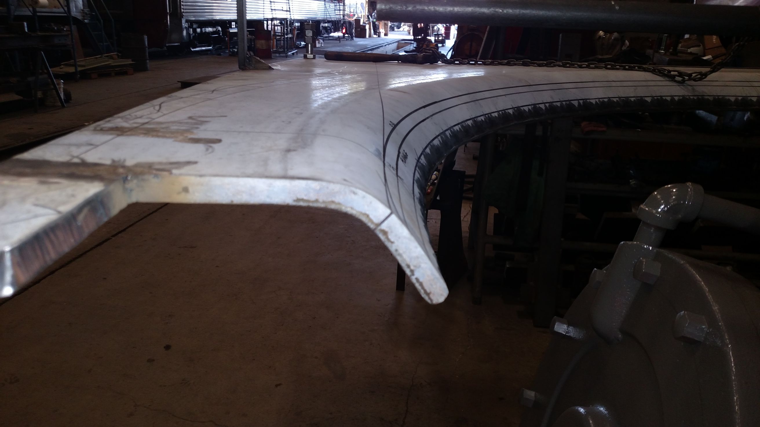
A slight bend in the tube sheet is visible here after a turn through the McCabe Flanger. Photo courtesy SPEC Machine.
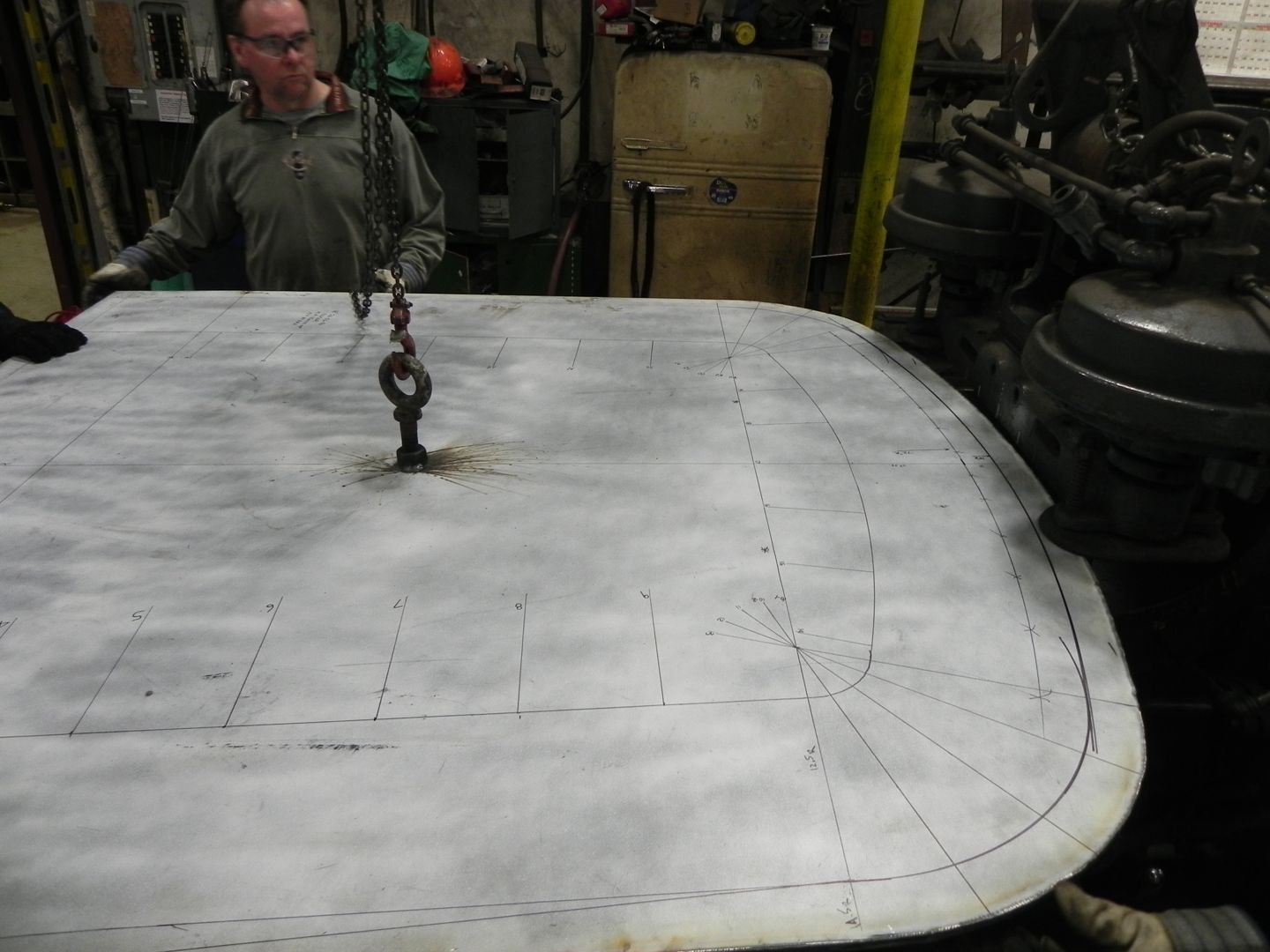
C&NW 1385’s new rear tube sheet takes shape. This is a view of a blend from a straight side to 12.5″ radius corner to 72″ radius crown sheet. Photo courtesy Gary Bensman. Mr. Bensman of Diversified Rail Services was contracted by Continental Fabricators to form the sheets for #1385’s firebox and tube sheets.