Welcome to the Chicago & North Western #1385 steam status blog! Follow along as we bring the 1907 American Locomotive Company 4-6-0 steam engine back to operating condition.
Mid-Continent Railway MuseumPosted on by Jeffrey Lentz
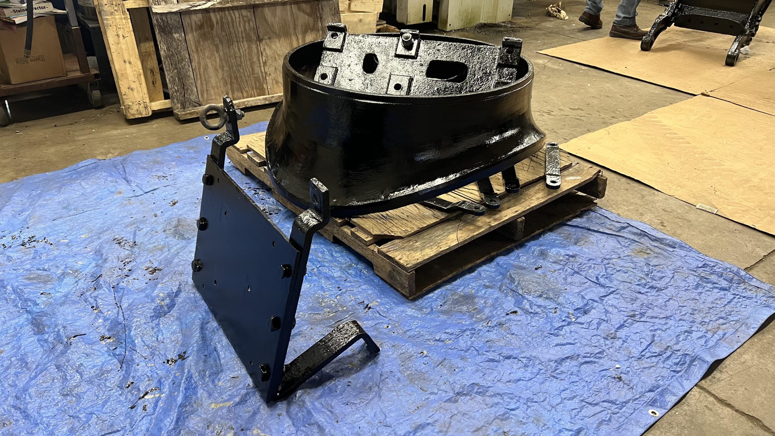
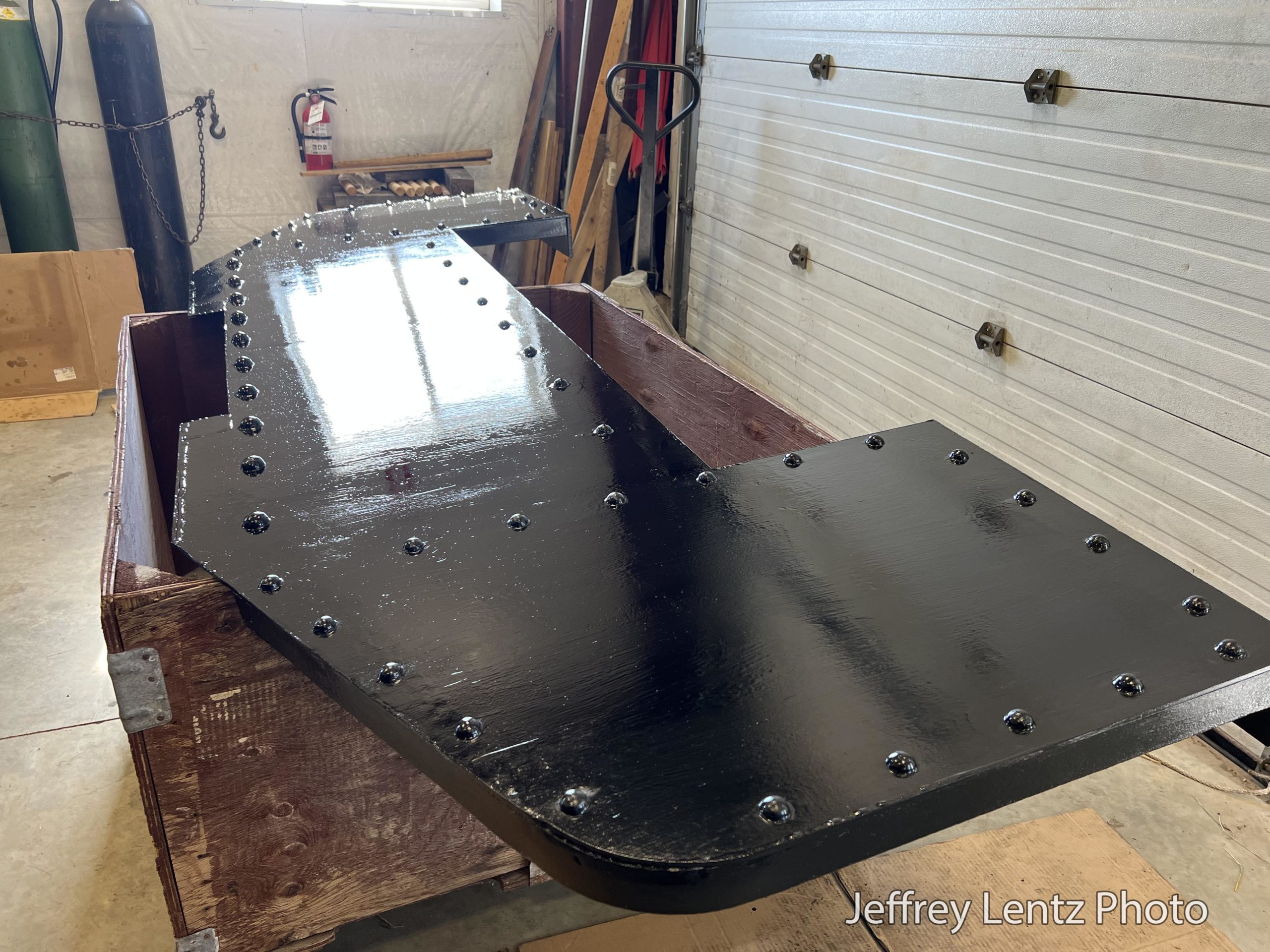
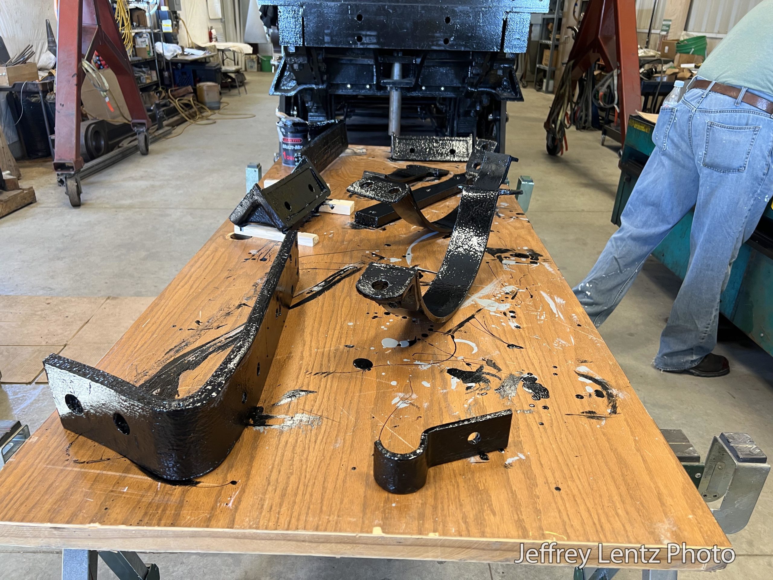
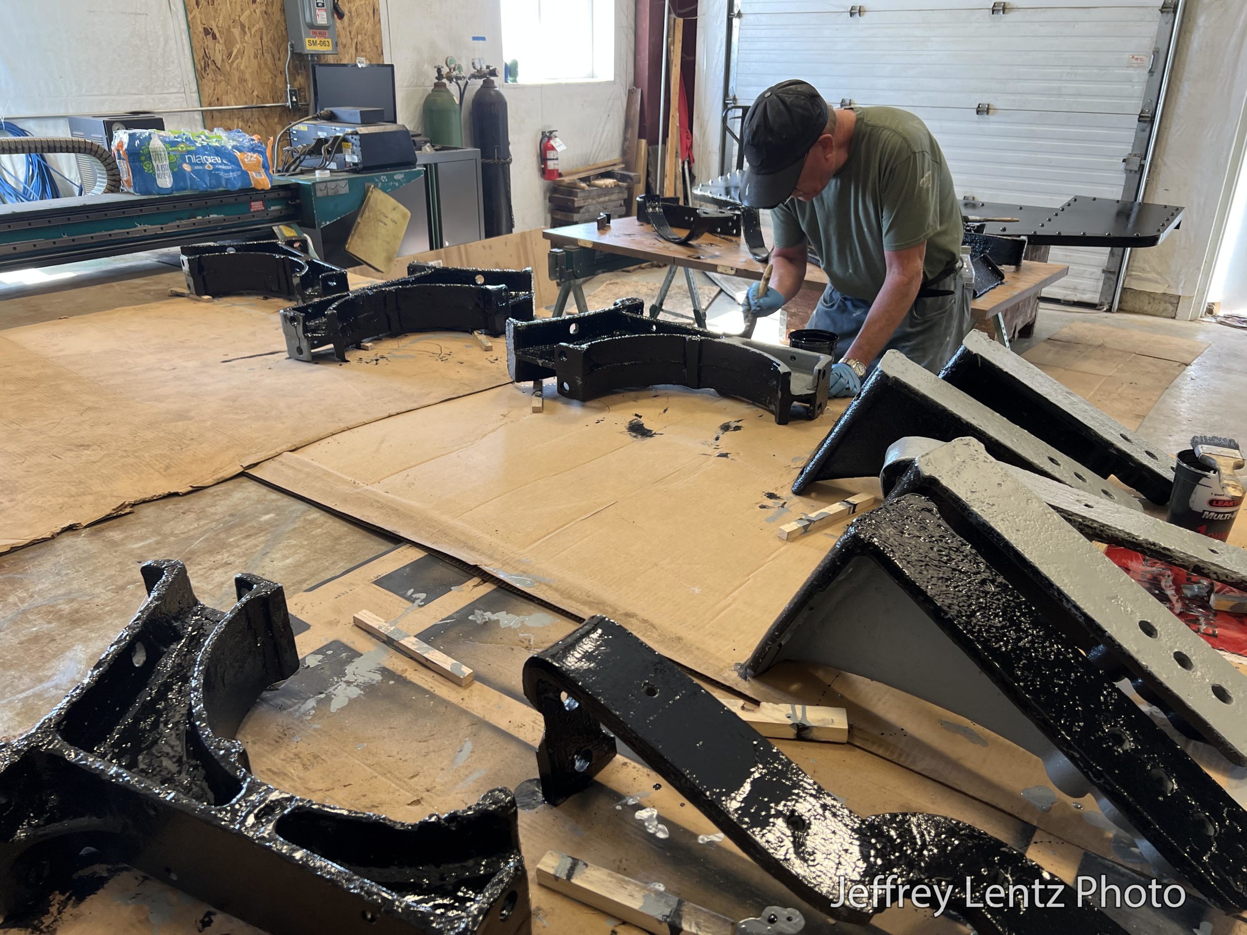
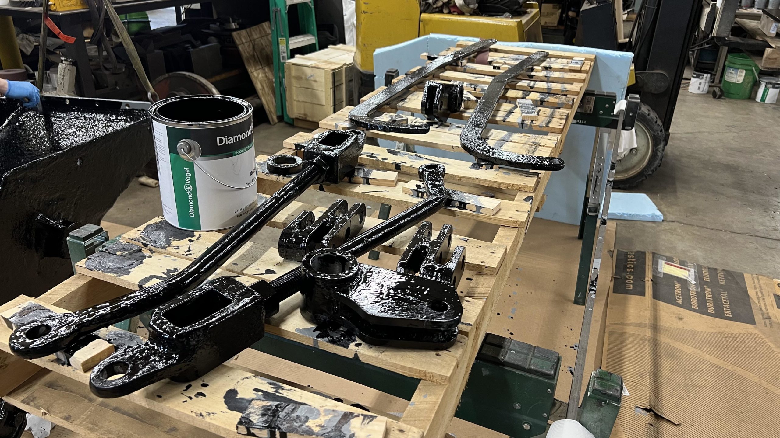
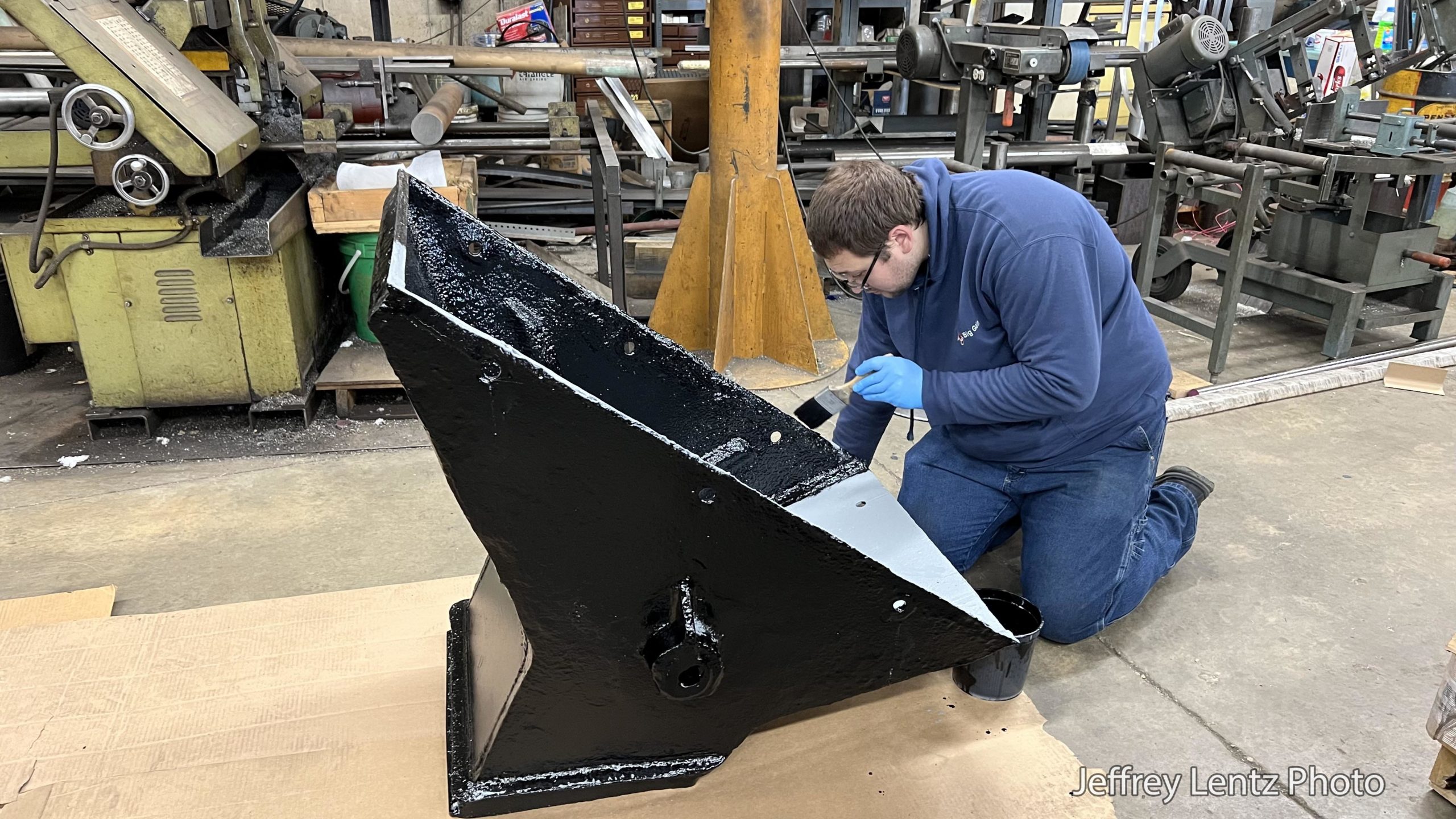
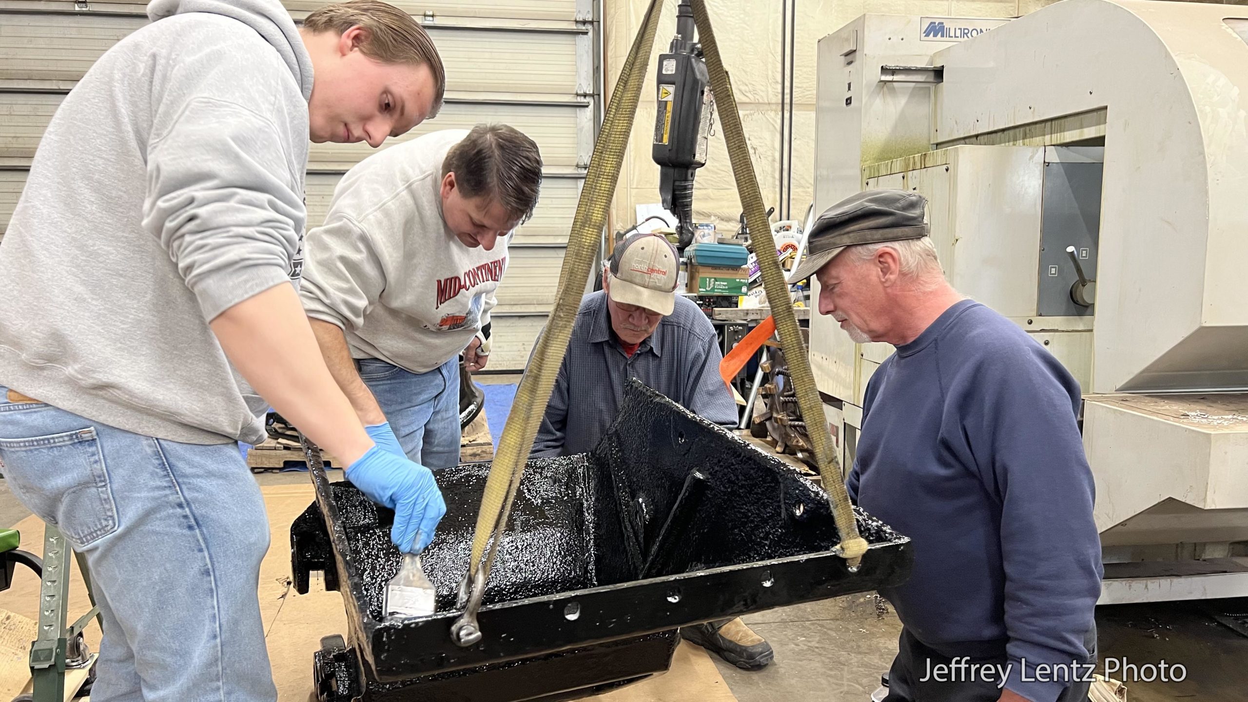
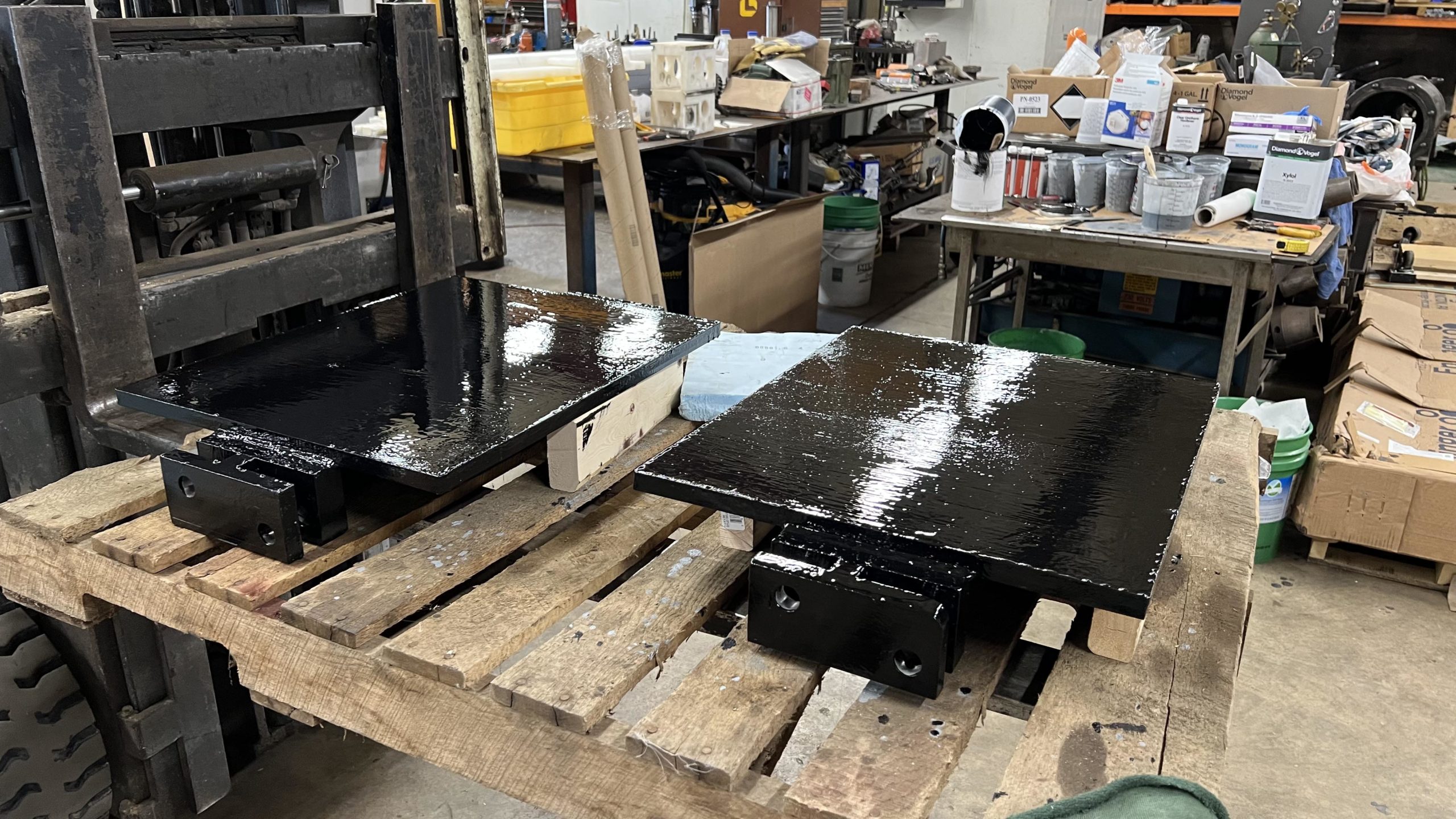
Mid-Continent Railway Museum volunteers gathered at SPEC Machine outside of Middleton, WI on Friday February 24th and Saturday February 25, 2023 to apply paint to numerous loose parts in preparation for installing the items onto the locomotive in the near future. Parts receiving primer and paint included the ashpan, brackets for the air tanks, bracket for the power reverse, sand dome parts, and numerous other components.
Turnout for both days of work sessions were great – almost too good on Saturday, making it necessary for some mandatory breaks while waiting for the paint to dry before adding additional coats.
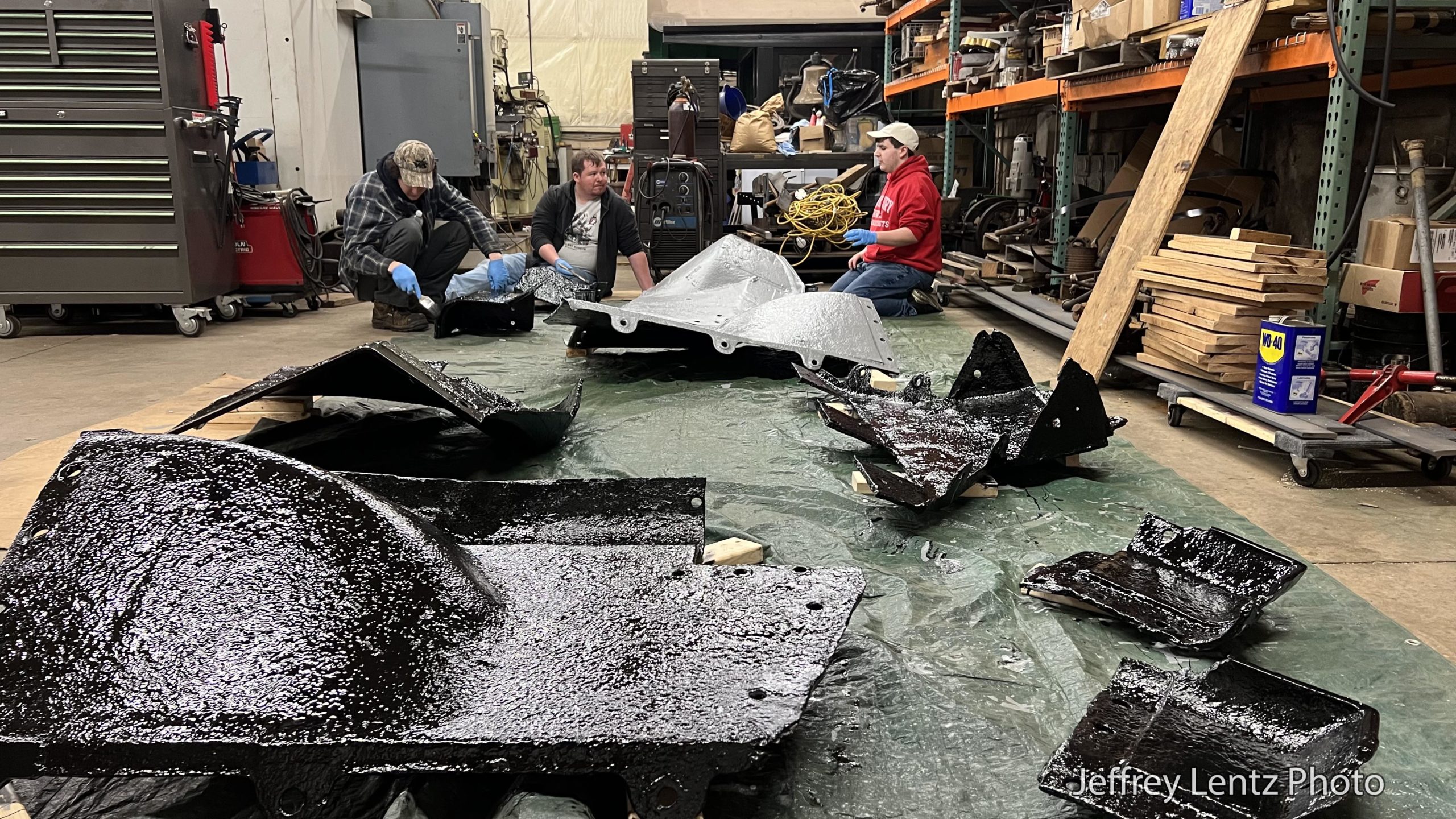
A big thank you goes out to the volunteers that participated – a few of whom signed up for museum membership just to be able to attend this session. The work was organized and led by Pete Deets and Ed Ripp of the 1385 Task Force. They were joined by volunteers Chuck B., Ross S., Larry S., Richard C., David S., James W., Robert D., Brayden E., Joey R., Jim B., Andy S., Gary B., Rusty S., Ken E., and Jeff H.
Thanks also go out to our host, SPEC Machine for opening their shop to our volunteers to make this session possible.
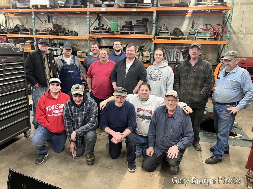
Volunteer crew on the afternoon of February 25, 2023. Gary Bjorge photo.Sand domeCab supportMiscellaneous brackets.Air reservoir brackets.Ash pan control connectors.Ash pan components.Ash pan component.Ash pan component.Ash pan doors.
Mid-Continent Railway MuseumPosted on by Jeffrey Lentz
Read to the end to see how you can volunteer to help bring 1385 back to operation!
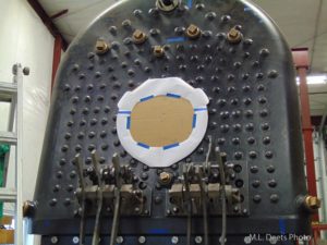
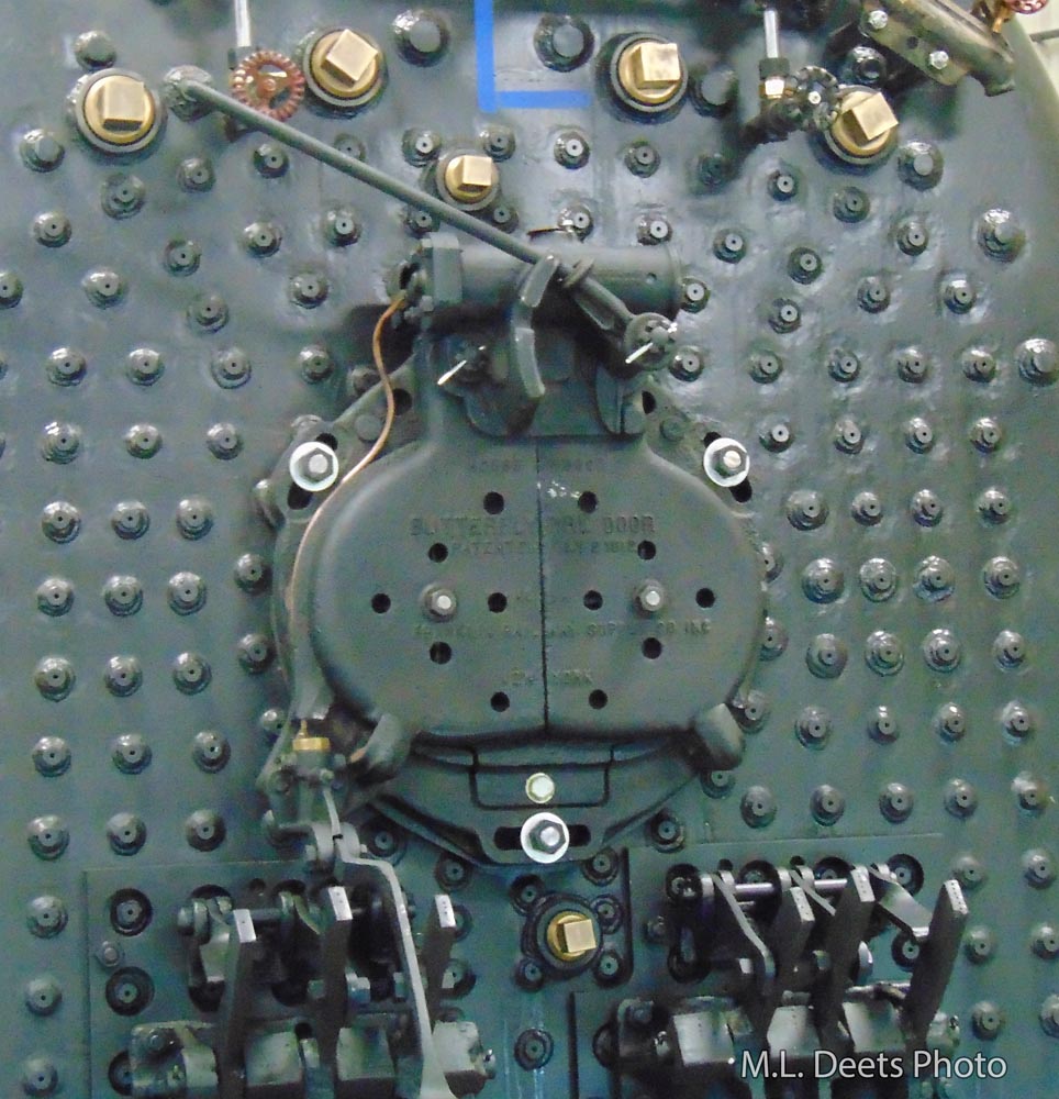
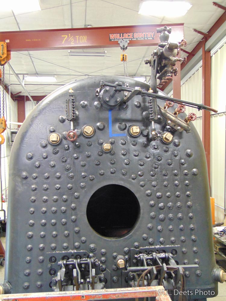
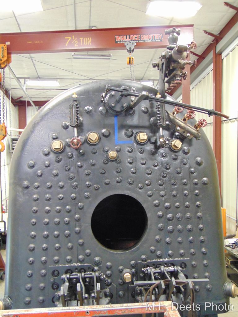
The next fixture to be mounted on the backhead of 1385’s boiler is the firedoor – the fireman’s target. The Franklin air-operated Butterfly door had been completely rebuilt and was patiently waiting its turn to rejoin the 1385. Like other appurtenances mounted on the boiler the firedoor will have to utilize a spacer ring to allow for the height of the staybolt heads that stand proud of the boiler surface. As noted in earlier updates current construction codes require that the head of the staybolt stand above any weld.
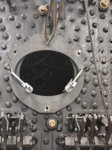
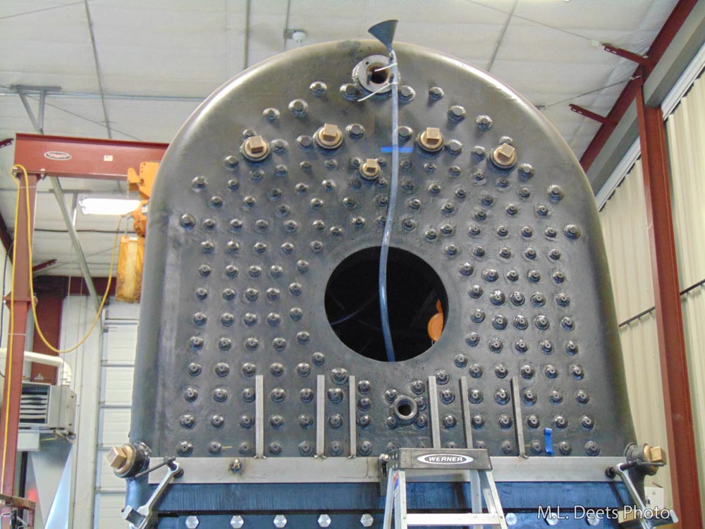
The first step in the process is a simple cardboard and paper template is set on the backhead to mark the position of each of the staybolts. The template for the adapter ring is an outline of the door mounting ring.
Paper and cardboard are used to create a mockup.
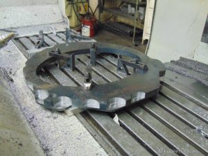
After the adapter ring has been cut out of a plate of steel it is set up on the bed of a CNC milling machine and the clearance notches for the staybolt heads are cut so the adapter and the door can lay flat on the boiler.
Machining the firedoor adapter.
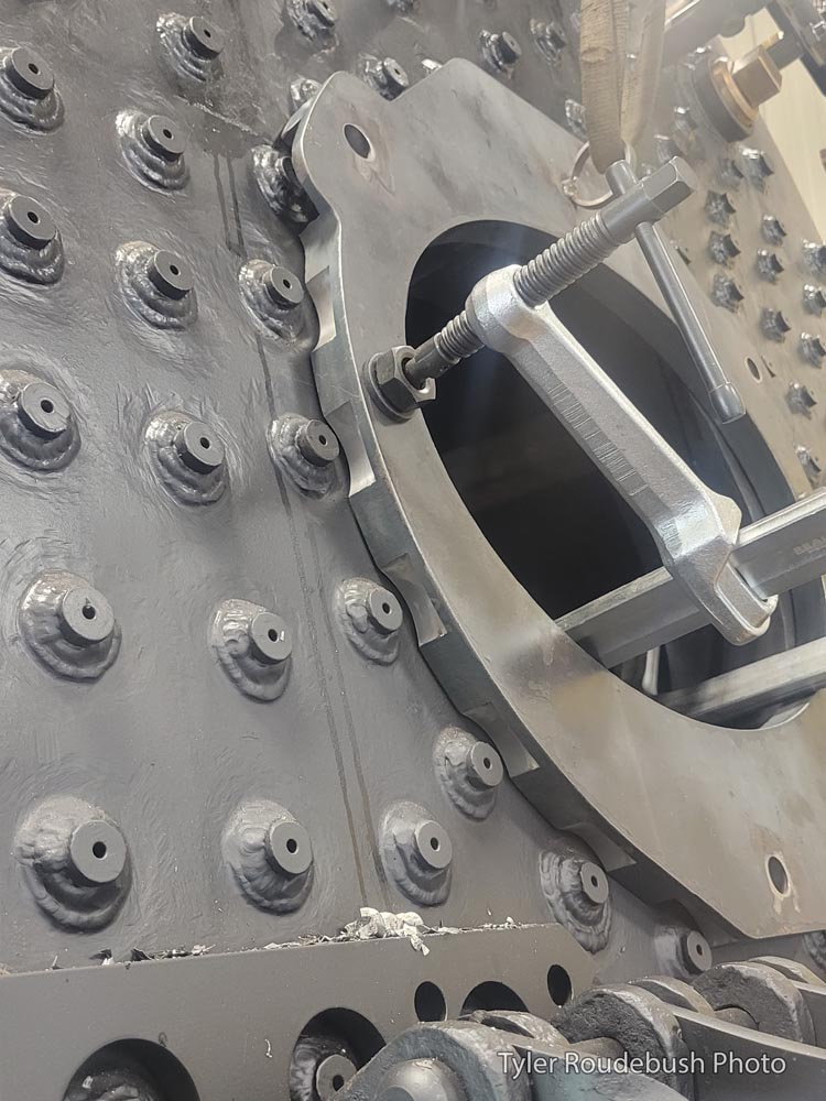
The adapter is then positioned and clamped to the backhead so the holes for the mounting studs can be drilled and tapped.
Fitting the adapter to the backhead.
Detail of staybolt clearance notches.
Once the drilling and tapping is finished the rebuilt door is mounted.
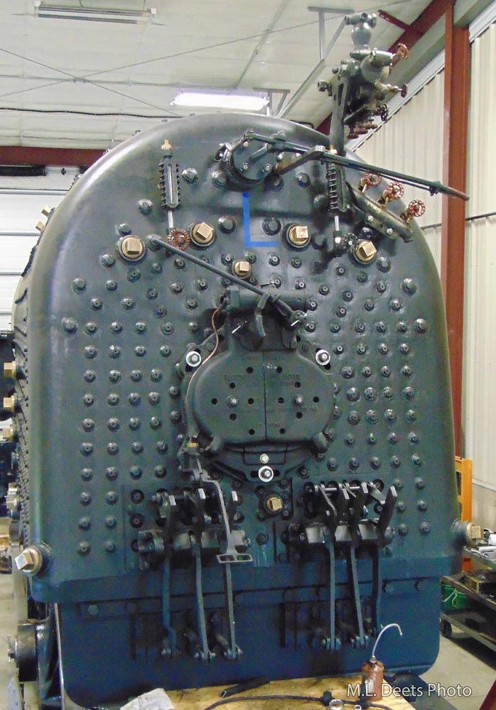
Firedoor mounted.
Here is a before and after comparison.
Before firedoor installation.After firedoor installation.
As an added bonus here is a short video clip of the door in action in its new home.
For extra credit here is a comparison of the backhead between the start of 2022 and late 2022. Installation visible included the lubricator, throttle, try-cocks, sight glasses, grates and grate shaker mechanism, and firedoor.
C&NW #1385 Volunteer Opportunity
Calling All Volunteers:
Who: YOU! What: Painting Party for parts of the 1385 Where: Middleton, WI When: Friday & Saturday February 24 & 25, 2023 Why: To help complete the Rebuild and Reconnect with the Engine
It has been far too long since we’ve had a 1385 Volunteer Session at SPEC Machine and we are going to cure that with a painting party! We will be painting many loose parts for the engine such as the ashpan, brackets for the air tanks, bracket for the power reverse, sand dome parts and many others. This is a Friday and Saturday session to allow business owner Steve at least a one day weekend.
We plan to start about 9 AM both days and knock off around 4 – 5 PM whenever a good stopping point is reached.
There will be a big pot ‘o chili for lunch and folks are encouraged to bring along something to share. Potluck is always such fun.
If you can make it one day or both please either sign up on our volunteering form (use button below) or previous volunteers can contact Pete Deets directly. RSVP is required so that enough chili can be cooked up.
Any time given will be thankfully accepted greatly appreciated.
**UPDATE** Due to insurance requirements related to this volunteer session being held at a contractor’s facility, this volunteer session will only be open to members of Mid-Continent Railway Historical Society. To learn more about becoming a member and the perks that come with membership, visit the Join Us page.
Mid-Continent Railway MuseumPosted on by Jeffrey Lentz
This is an older update that was delayed getting posted online. Thank you for your patience. — The Webmaster
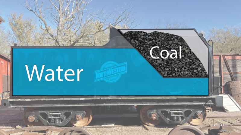
Adding Cistern Piping
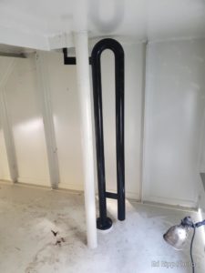
In October, volunteers continued working on Chicago & North Western #1385’s tender cistern ports. This included installing bottom fill piping and ports for connecting to a canteen car, otherwise known as an auxiliary tender.
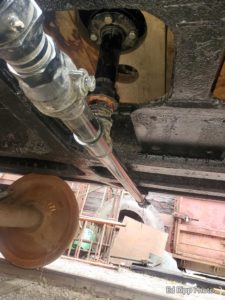
Bottom fill exterior piping.
Bottom fill pipe outlet installed.
Cistern port.
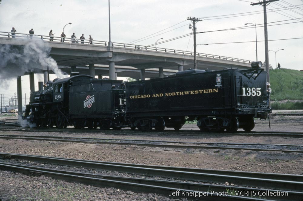
On Mid-Continent’s shortline railway, 1385’s tender has more than enough water capacity to keep 1385 steaming, but a canteen car becomes more important when water sources are harder to come by. Mid-Continent’s canteen car, which offers an additional 12,000 gallons of water capacity, was frequently found trailing 1385’s tender when the locomotive was venturing around the Upper Midwest on mainline excursions. Mid-Continent’s canteen car is currently on display near the museum’s water tower.
C&NW 1385 with canteen car at Butler, Wis. for “Butler Railroad Days” event on June 5, 1983. Jeff Kneipper photo. MCRHS Collection.
Test Filling the Tender
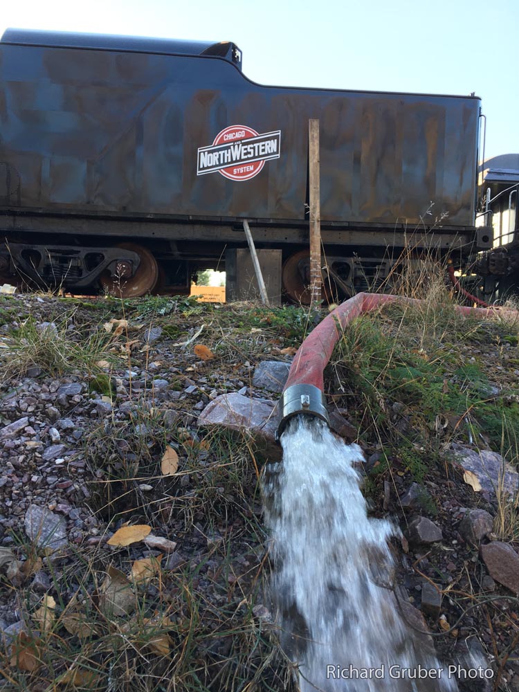
On October 29th, a team of volunteers including Pete Deets, Kyle Gerke, Richard Gruber, and Ed Ripp filled 1385’s tender with water up to its maximum capacity. This was done for testing purposes.
Although the Mid-Continent’s Engine House has a faucet connected to the museum’s groundwater well, that system lacks sufficient capacity to fill a tender in a timely fashion. For a quicker fill time, volunteers utilized a submersible pump that had last been used when steam was in regular service, and pumped the water directly out of the adjacent Baraboo River using a 2-inch hose. The river water contains many impurities and will not be used when running steam in the future, but for doing a test fill of the tender, Baraboo River water would work just fine.
Attached to the hose was a water meter to allow an accurate measurement of the gallons pumped into the tender. While filling the tank, one person watched the water meter and another person was on top of the tender marking a board with measurement lines. This was necessary because 1385’s tender has a new cistern. These measurements will be transcribed to a water level meter used by engine crews in the future.
Water meter
Kyle, kneeling atop the tender, adds water measurement markings to a measuring board.
Draining the tender at the end of testing.
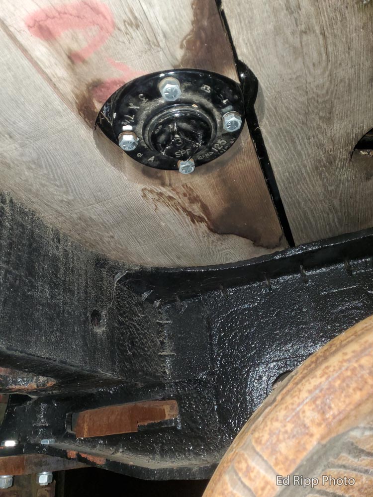
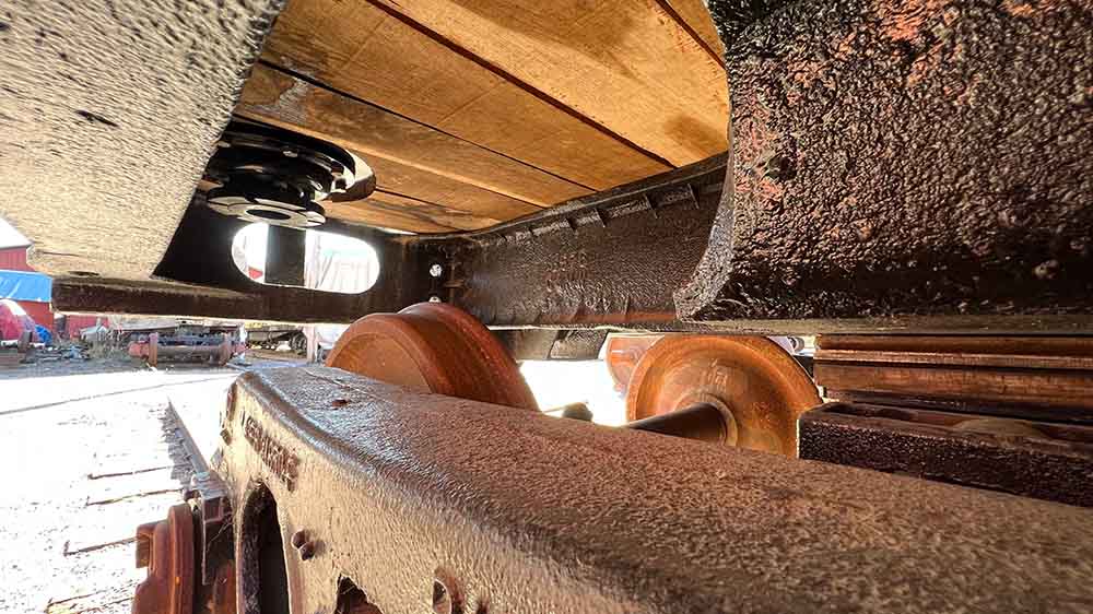
Measurements were also taken of the drawbar pocket and the center of the rear coupler when the tender was empty and again when full. Marks were also made on each truck at the bolster and pedestal jaw at empty, half-full, and full to see how much the springs settled with the differing weights.
During this testing, some additional to-do items were discovered and added to the work list.
Upcoming Work
Volunteers kept busy preparing for and hosting Santa Express in November and December no additional work sessions on the 1385’s tender were held in 2022, but in December the tender was moved inside the Engine House to permit work to continue during the winter months. The first winter work session inside the Engine House is tentatively scheduled for January 7th and 8th. Volunteers may also be working on Western Coal & Coke #1 and performing some general shop cleanup/organization work.
Persons interested in volunteering for this or future volunteer sessions should contact Ed Ripp, General Foreman of Steam Power, or fill out the volunteering inquiry form.
Mid-Continent Railway MuseumPosted on by Jeffrey Lentz
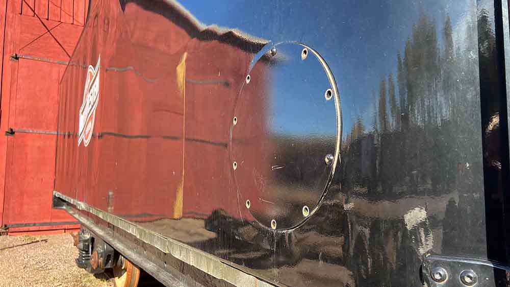
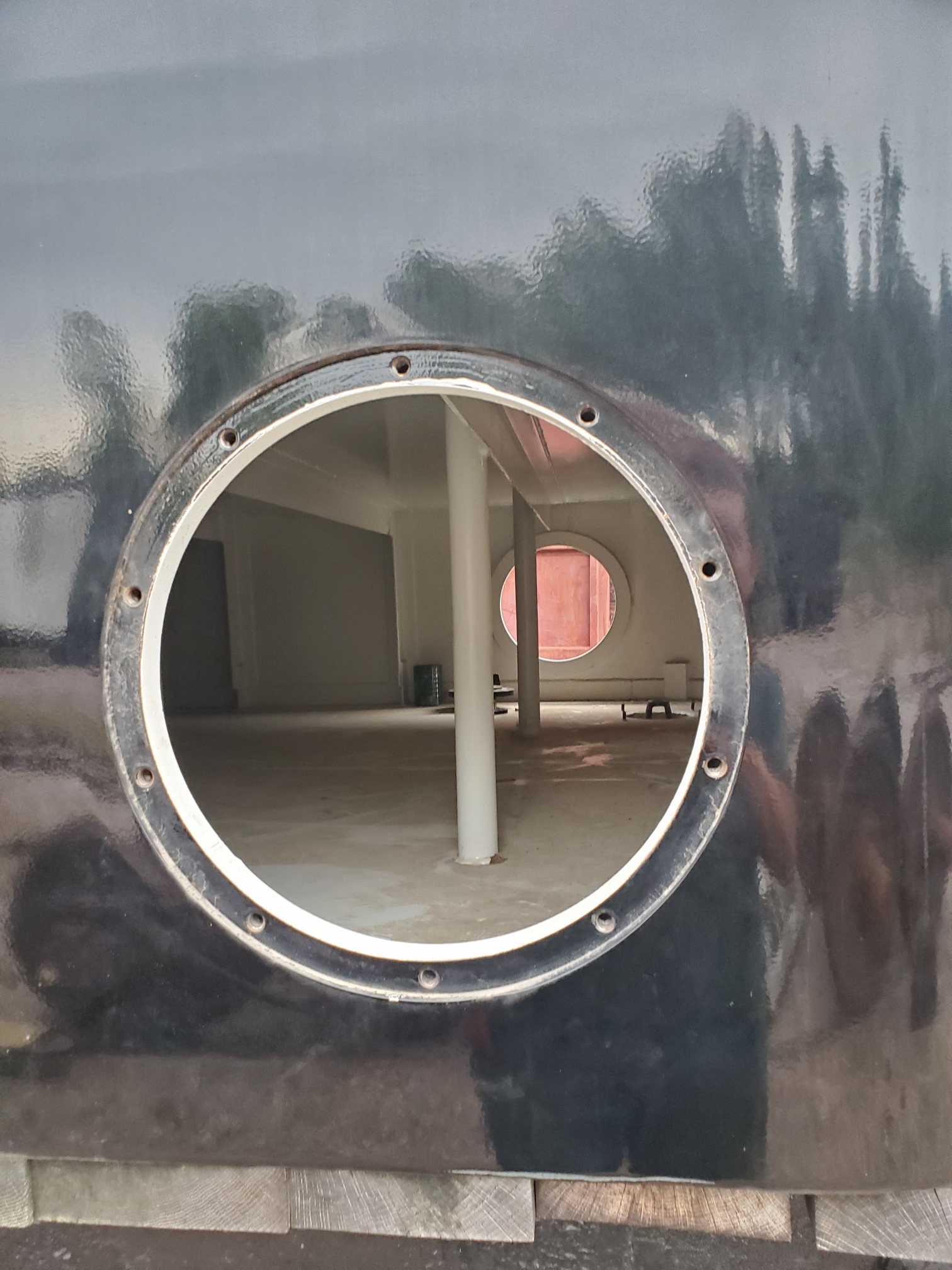
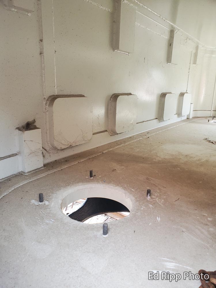
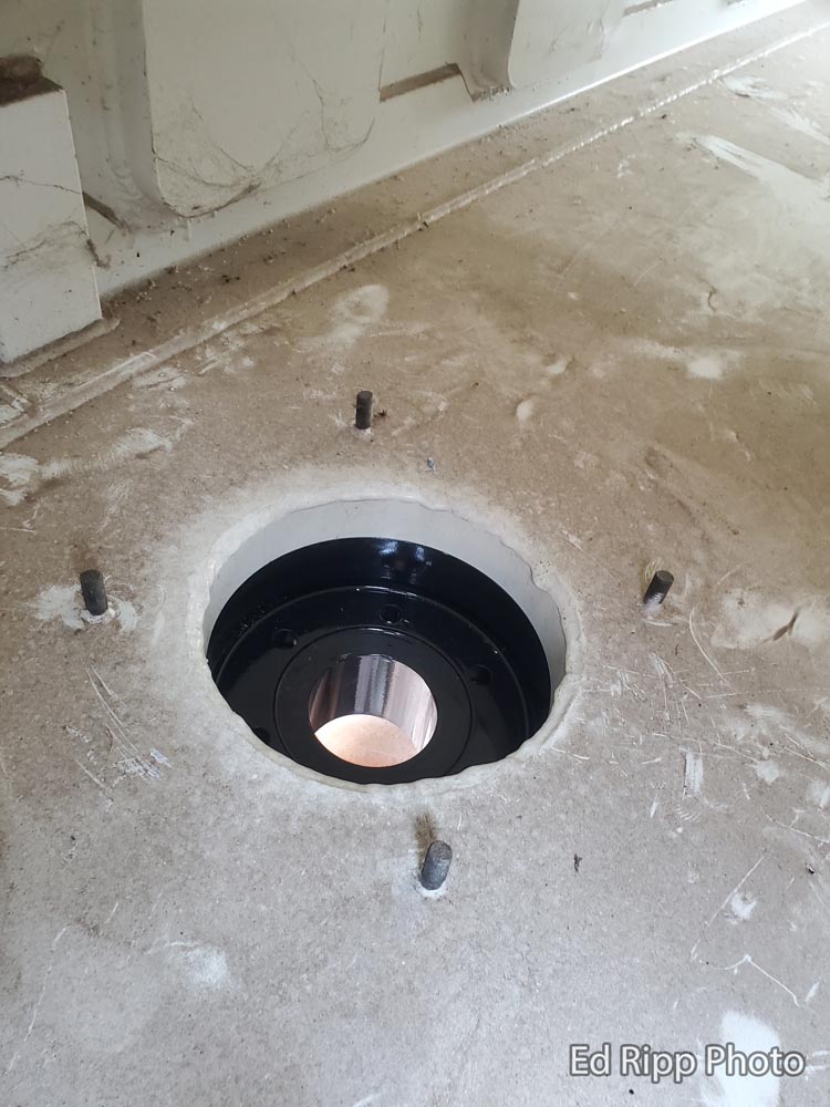
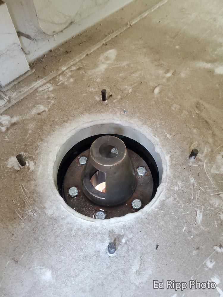
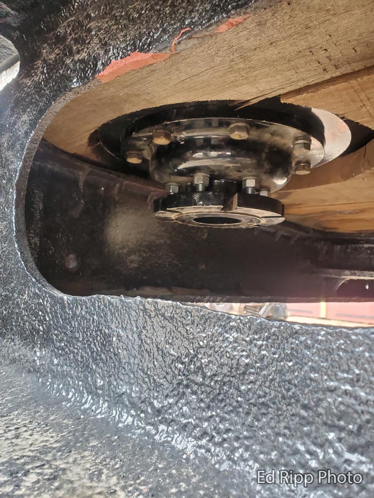
There was a volunteer work session during the weekend of September 17 and 18, 2022 that focused on the CNW 1385 tender. Work concentrated on closing up the cistern ports. The ports allow water either in or out of the cistern or water tank.
One of the next steps is to fill the tender with water. This will allow project volunteers to see how much the tender settles down on its springs with the added weight of the water as well as to verify the function of the different seals.
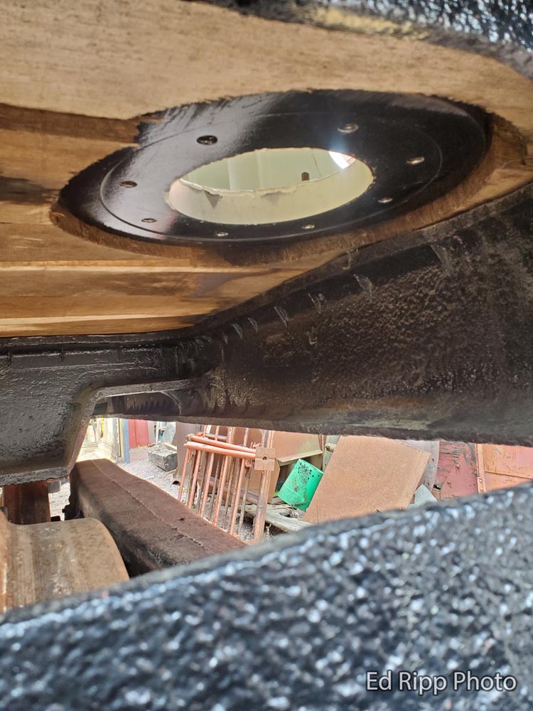
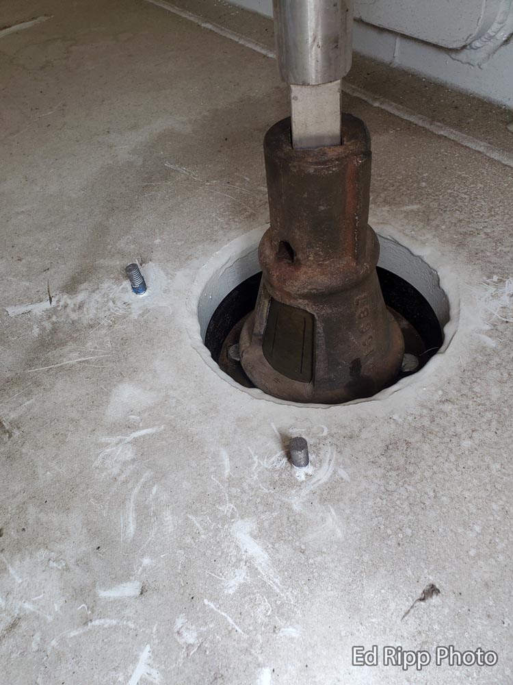
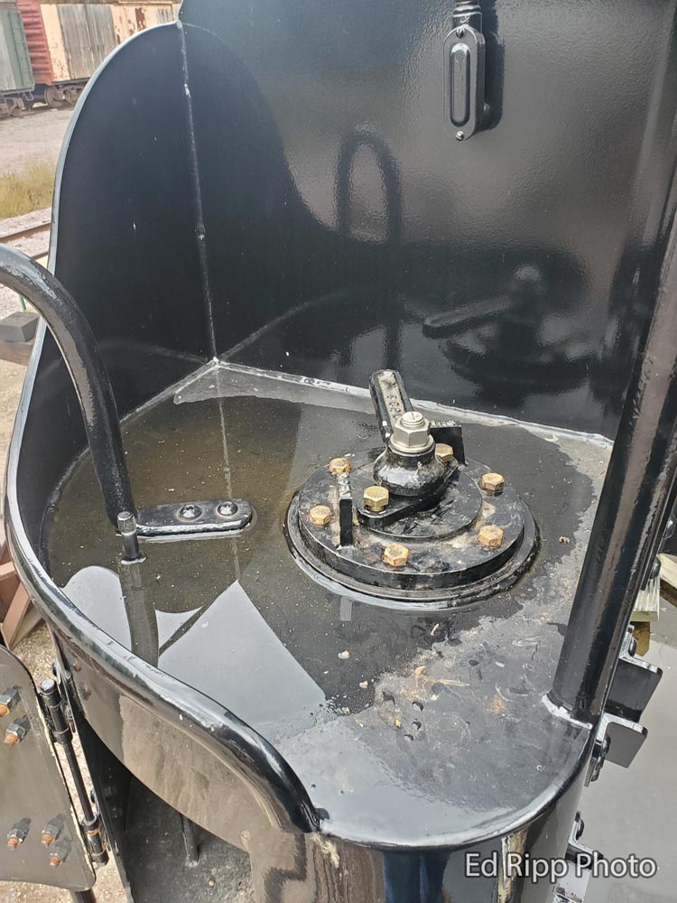
Access panels on the sides of the tender allow volunteers to reach some of the harder-to-access cistern valves.
Right side valve access panel closed.Right side valve access panel open.Bottom view of the cistern valve well mounting flange.Inside view of the left side cistern valve well mounting flange.Inside view of the left side cistern valve well only installed.Inside view of the cistern valve seat installed.Bottom view of the right side cistern valve well and valve seat mounted.Inside view of the right side cistern valve with the operating rod installed.Top side view of the right side operating handle assembly.Bottom view of the left side cistern valve well and valve seat mounted.
Thank you to volunteers Lloyd H, Steve P. Sr, Jay S, Ross S, and Larry S for helping out during the work session.
C&NW #1385’s tender has a capacity of 7,500 gallons of water – about the same as an 18 foot diameter swimming pool! When filled, the water will add over 31 tons to the tender’s weight.
Stay tuned for Part 2 of this update, coming soon…
Mid-Continent Railway MuseumPosted on by Jeffrey Lentz
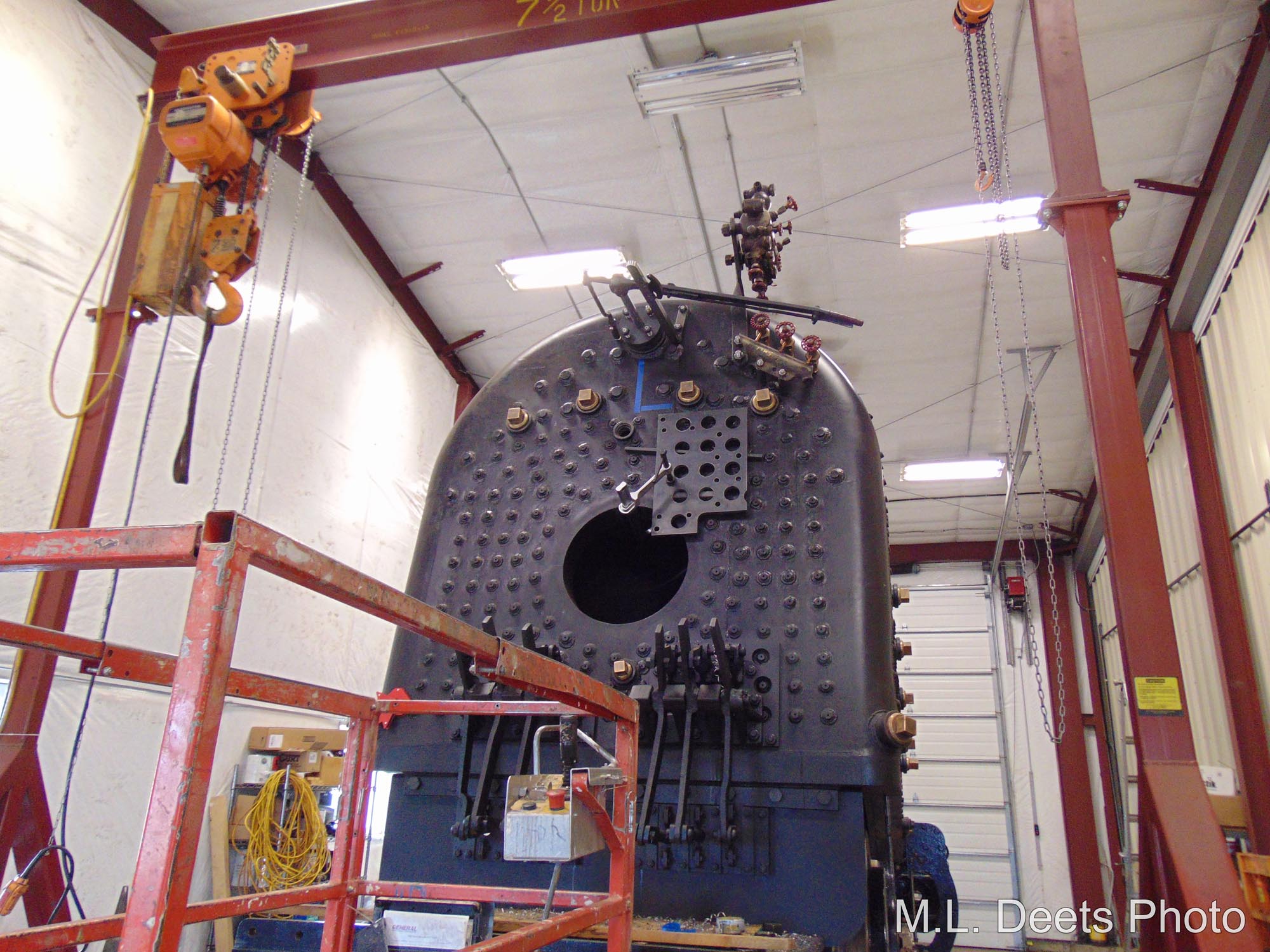
What are those 3 most important things about a boiler? Water! Right Again! How can you tell where it is at? Peer through the looking glass although it is more commonly known as the water glass, sight glass or gauge glass.
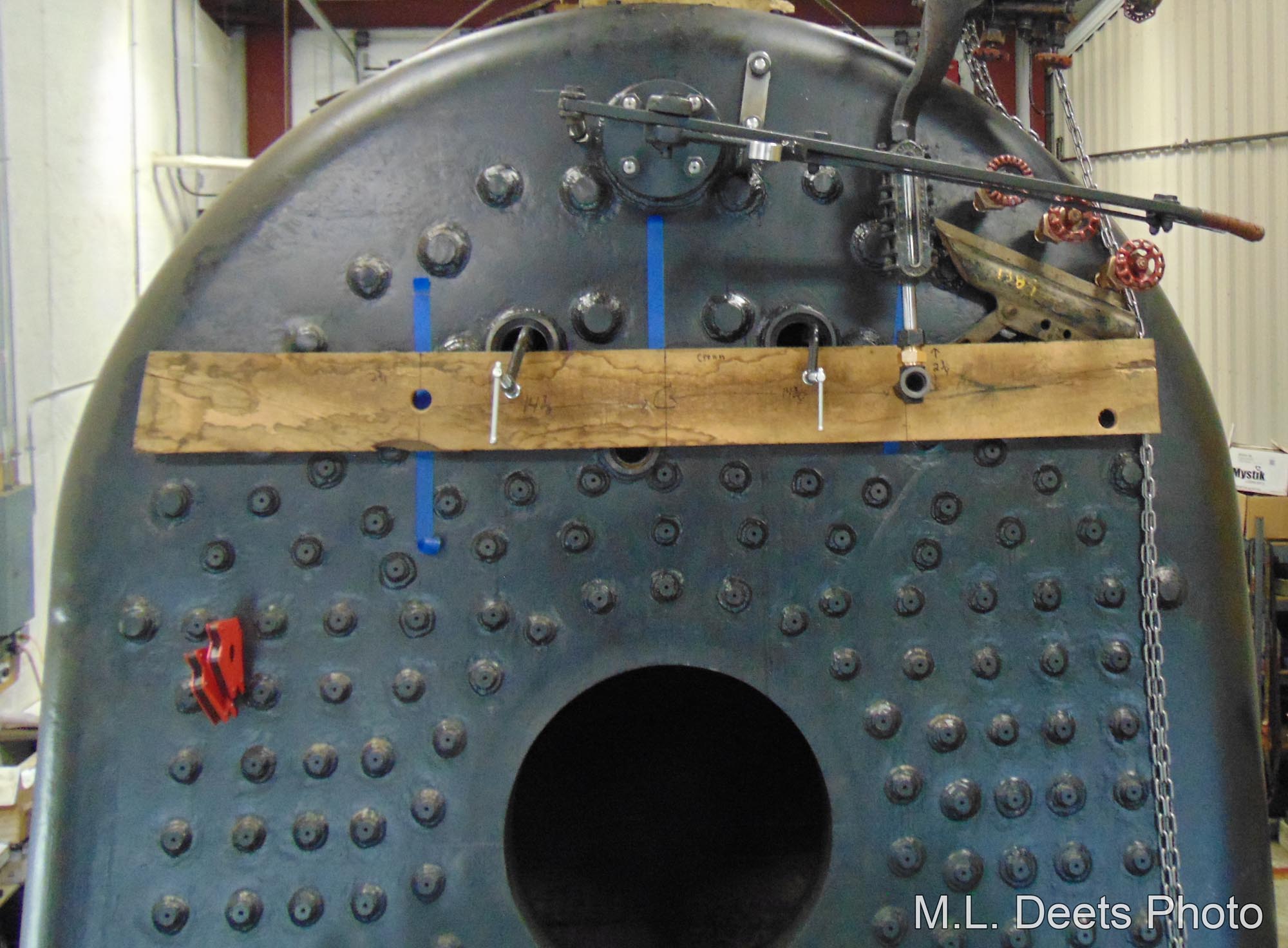
The 3-dimensional chess continues with placing the water glasses on the backhead of the boiler. The board clamped in place served not only as a way to locate both FRA-required water glasses correctly but to facilitate checking for enough clearance around and under the other appurtenances already in place.
Water glass mockup.
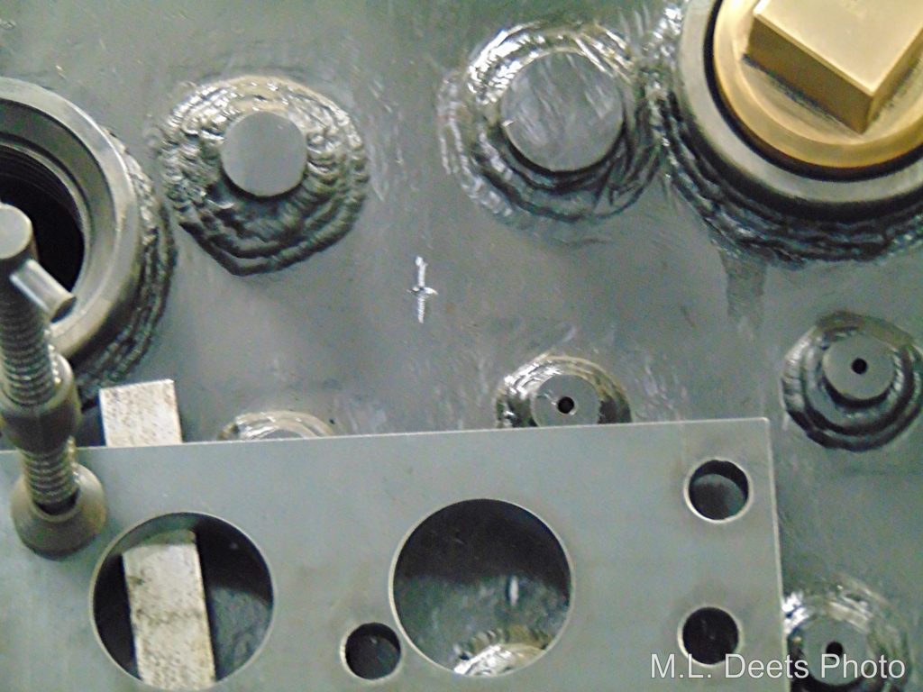
The metal plate clamped to the backhead serves as a nice flat baseplate for the magnetic based drill used to drill the holes for the appurtenances and studs.
Baseplate mounted to assist drilling water glass hole.
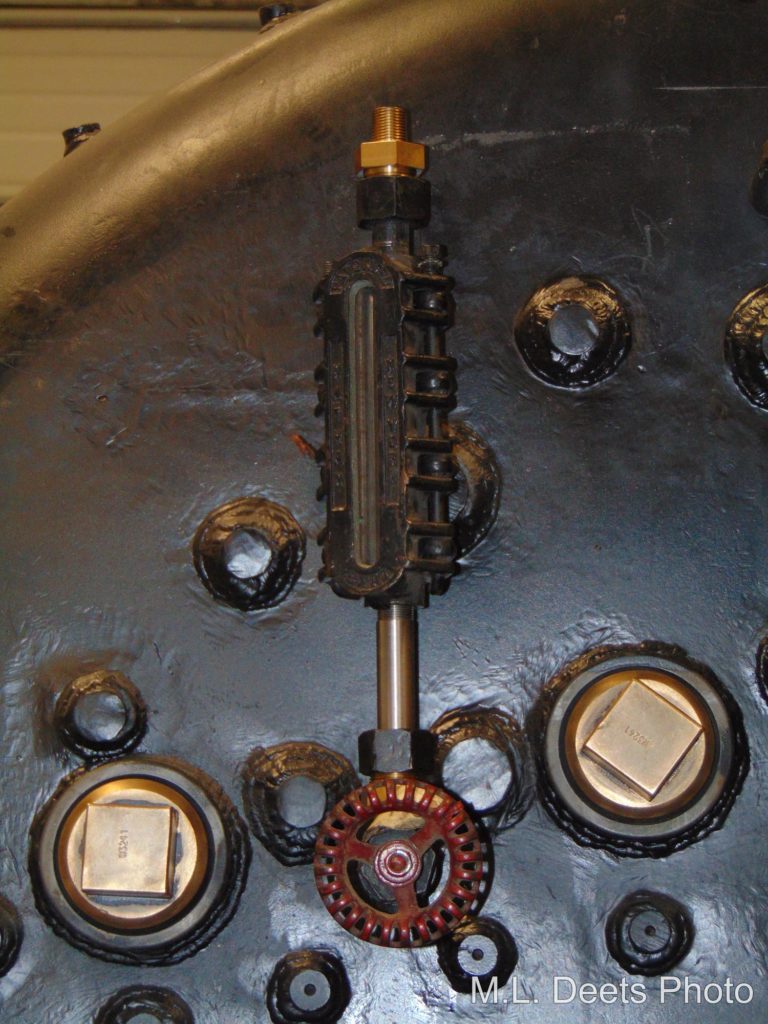
The plate is lined up for drilling of the hole for the first glass. The result is seen here. And like the bottom try-cock the lowest indication of the water glass is 4” above the highest point of the crownsheet per C&NW practice.
First water glass installed.
The plate was then moved to the fireman’s side where the single glass had been mounted on the original boiler and X marks the spot.
Water glass hole location marking.
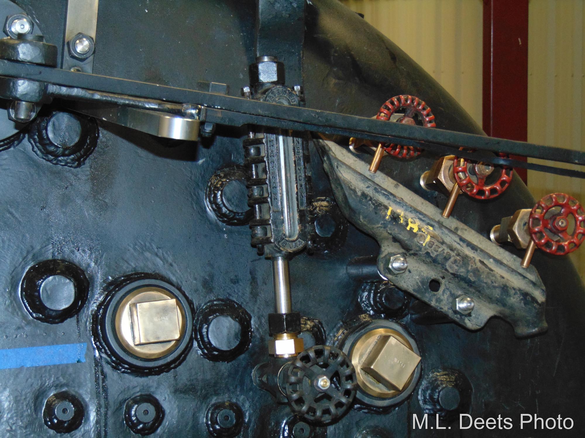
After drilling and tapping in the threads the second glass is seen here.
Second water glass installed.
With both glasses mounted the backhead is looking more like a locomotive all the time.
Both water glasses installed on backhead.
A volunteer session is being held on September 17 and 18 to work on the the C&NW #1385 locomotive tender. Tasks planned include filling the tender with water to check the truck spring compression and making any necessary adjustments. Additional work planned includes brake pipe fabrication. Persons with experience heating/bending pipe are highly encouraged to participate in this session. If there is sufficient help, other tasks in the Engine House will be tackled. Sign up by contacting project lead Ed Ripp or using the form on our Volunteering page.