As 2020 draws to a close, the Mid-Continent Railway Museum Restoration Department is pleased to look back at this challenging year with a sense of teamwork and accomplishment. All things considered, we had a good year but volunteer work at the museum was shut down from mid-March through early June, reducing our annual planned work sessions by 25%. On June 6th volunteer activity resumed at the museum, and thanks to savings funds and the generosity of donors we were still able to make headway on projects without using any of the museum’s operating funds.
To help navigate the pandemic more frequent work sessions were held to spread out the work and the volunteers. The level of dedication was impressive as volunteers were working in the Car Shop with great regularity up to the end of October. Even with the museum closed to the public and pandemic occurring a total of (28) different volunteers took part in the work sessions and collectively put in over (265) man-days of work at the museum throughout the year. An equal amount of time was put in by volunteers working on projects at home throughout the year.
Thank you to everyone that helped us by volunteering and/or by donating to preserve and restore the historic railroad equipment at Mid-Continent. The accomplishments listed in this report could not be possible without the dedicated group of volunteers. Summarized below is a list of the progress and accomplishments for the Restoration Department in 2020.
East Jordan & Southern combine #2
The west side letter board was completed with the filling of screw and nail holes, sanding and priming. The east side letter board required patching, installation and fabrication of the north end extension which was missing. That was followed by filling, sanding and more priming to complete the letter board. The north end drip boards were also installed. Three of the four platform steps have been taken apart and are in the process of being rebuilt. Work was also started on cleaning up the trucks. Remnants of pinning striping were uncovered, likely dating back to the 1902 refurbishment by Hicks Locomotive & Car Works.
In the second half of the summer work moved to the interior of the car. The east side wall boards had previously been removed from the car. The paint was stripped from these boards and the wall is in the process of being rebuilt. Much of the paint on the west side wall has also been removed although the wood needs to be cleaned up with chemical stripper. Also work was done on the floor to replace some bad wood and missing boards. Finally, all the clerestory windows were removed. The stained glass will be remounted in new frames during the winter months.
-
-
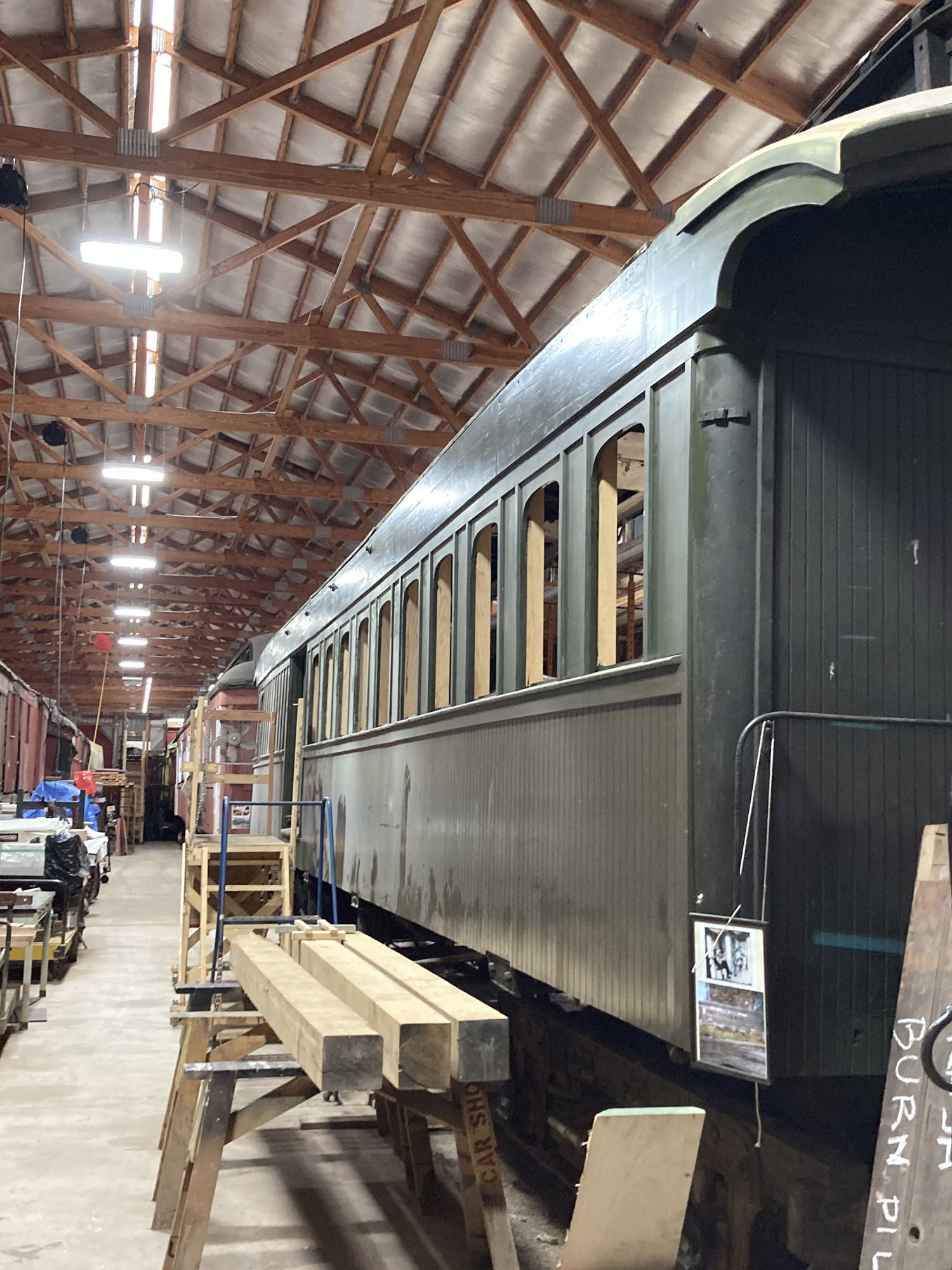
The east side of the EJ&S #2 with the letter board completed.
-

-
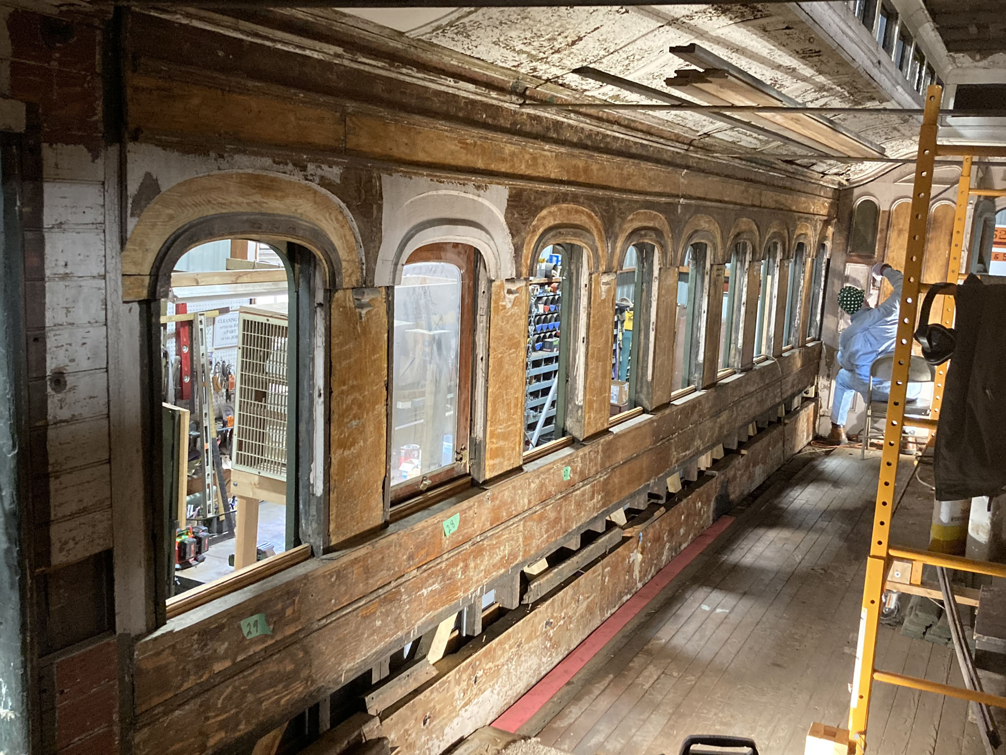
Interior paint stripping in progress in the passenger section.
Related Links:
EJ&S # 2 Restoration Updates
EJ&S #2 Roster Page
Duluth South Shore & Atlantic DULUTH Sleeper
The year kicked-off by successfully meeting the fundraising goal for the “Buy A Berth” fund drive. These funds enabled the contractor to replicate the missing berths for the car. By late summer the new upper berths and lower berth seat ends were all constructed. In addition replacement cast brass claw feet were made and polished for the new seat end. With the new berths completed efforts turned to stripping the old finish (shellac) off
of the original upper berths and seat ends. Presently all of the berths and seat ends are awaiting the application of the stain and varnish.
-
-
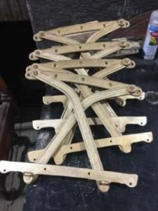
One of four existing berths stripped in prepraration of being stained and varnished.
-

-
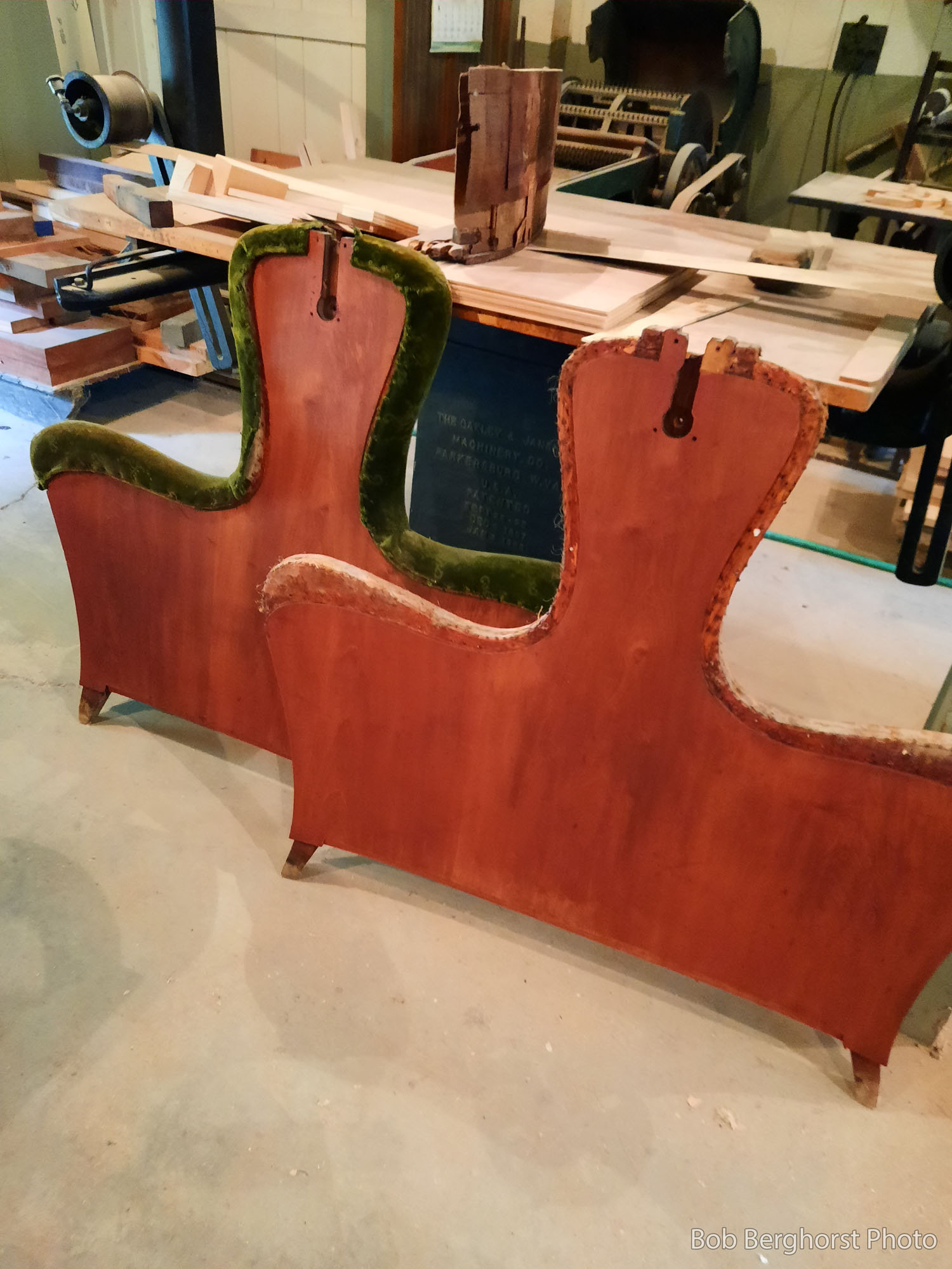
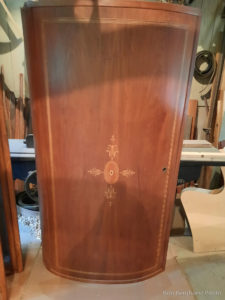
Two of the existing lower berth seat ends stripped in preparation of being refinished.
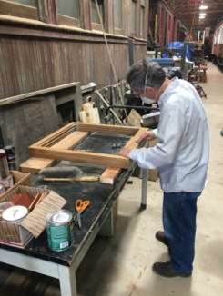
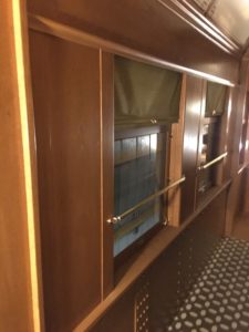
Inside the car volunteers focused on working in the sleeping compartment by removing 9 of the 10 veneer headlining ceiling panels that were water damaged and couldn’t be salvaged. In addition all interior hardware (i.e. berth pulleys, latches, roller shades) was removed so the parts can be cleaned and restored. A prototype of the mahogany berth partition trim piece (an overlay) was developed and test fit in the car. Also all of the existing seat cushions (backs, bottoms and head rests) from the sleeping compartment of the car were removed. In early fall samples of missing woodwork in the sleeping compartment were removed from the car so the parts can be replicated as part of the 2021 work.
-

-
Duluth lower interior roof after the headlining panel was removed.
-
-
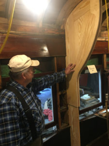
Fred B. test fits the berth partition overlay.
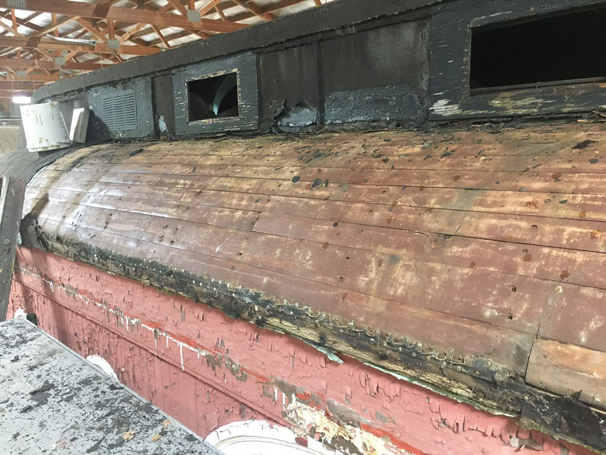
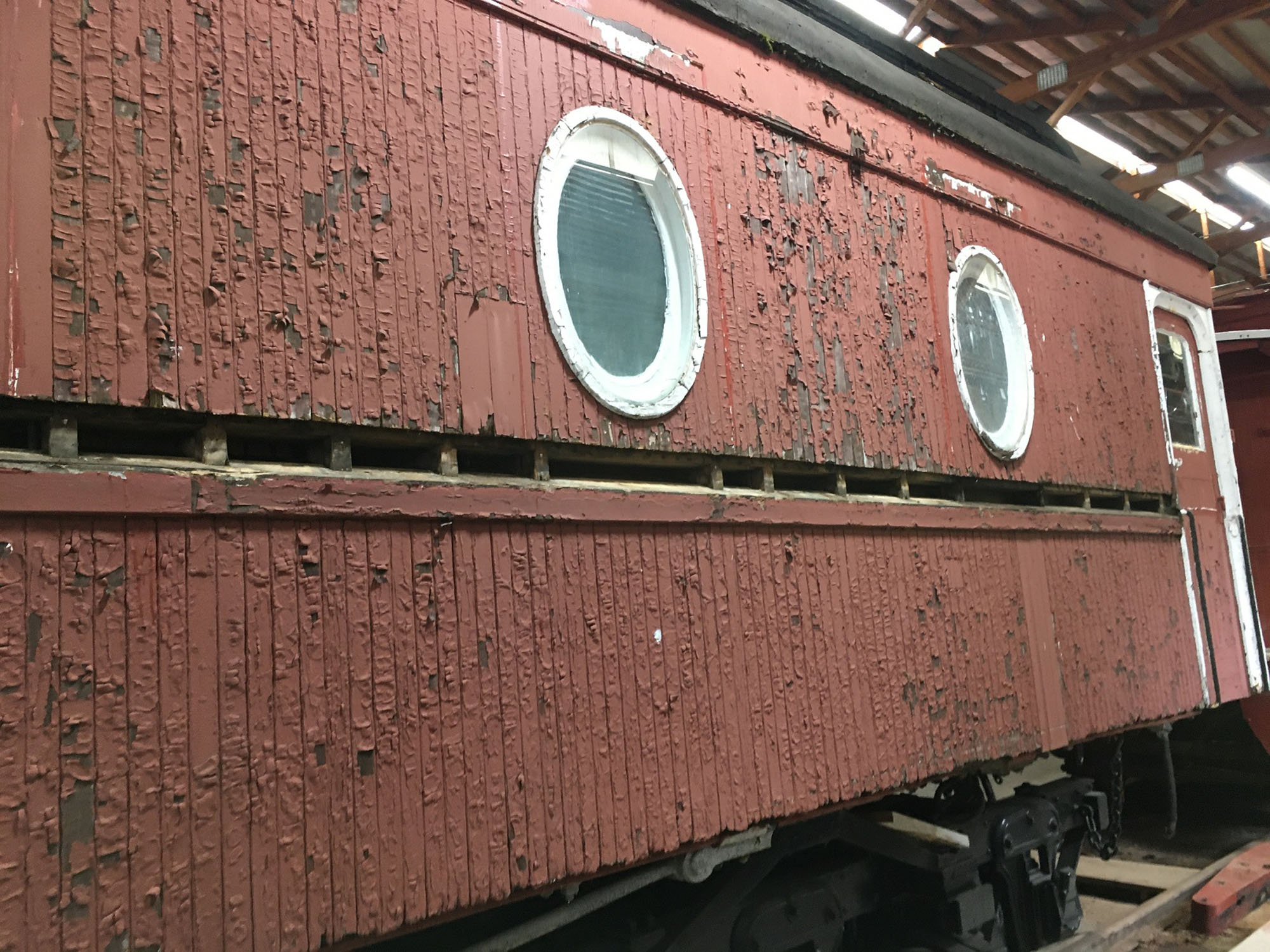
On the exterior of the car the window sills on both sides of the car were removed as all of it was rotten and couldn’t be salvaged. In addition, volunteers started to remove the existing rolled roofing material off of the roof. Plans call for removing the balance of the rolled roofing in 2021.
-

-
A portion of the roofing removed off of the DULUTH
-

-
Window sills removed from the DULUTH’s west side.
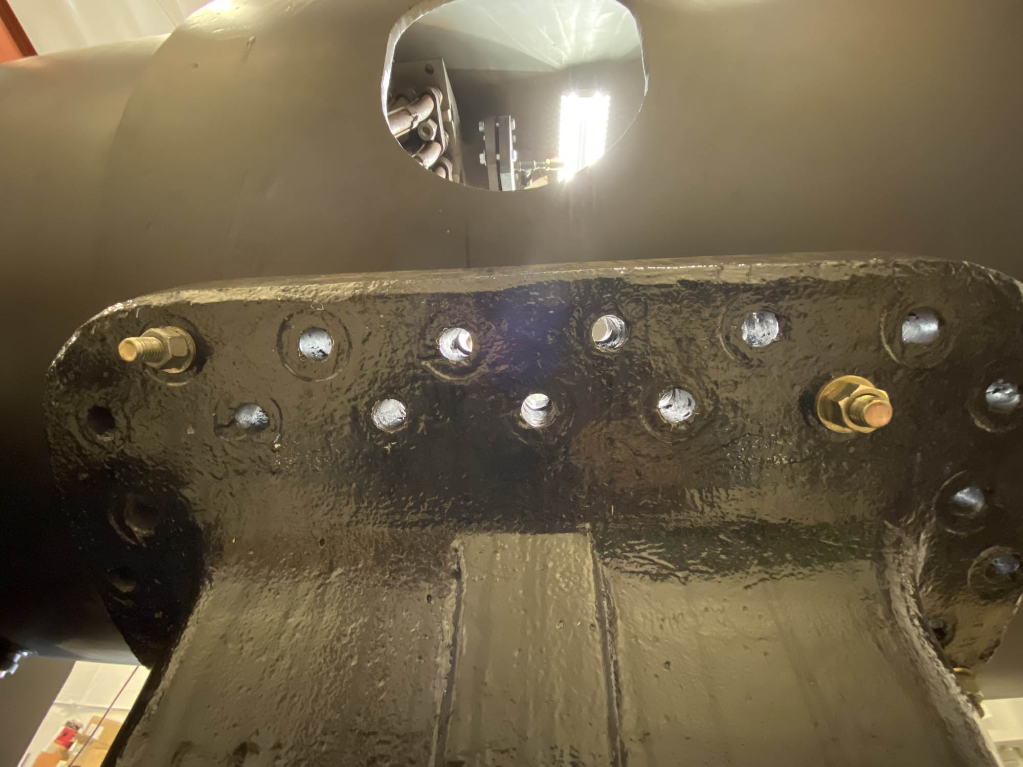
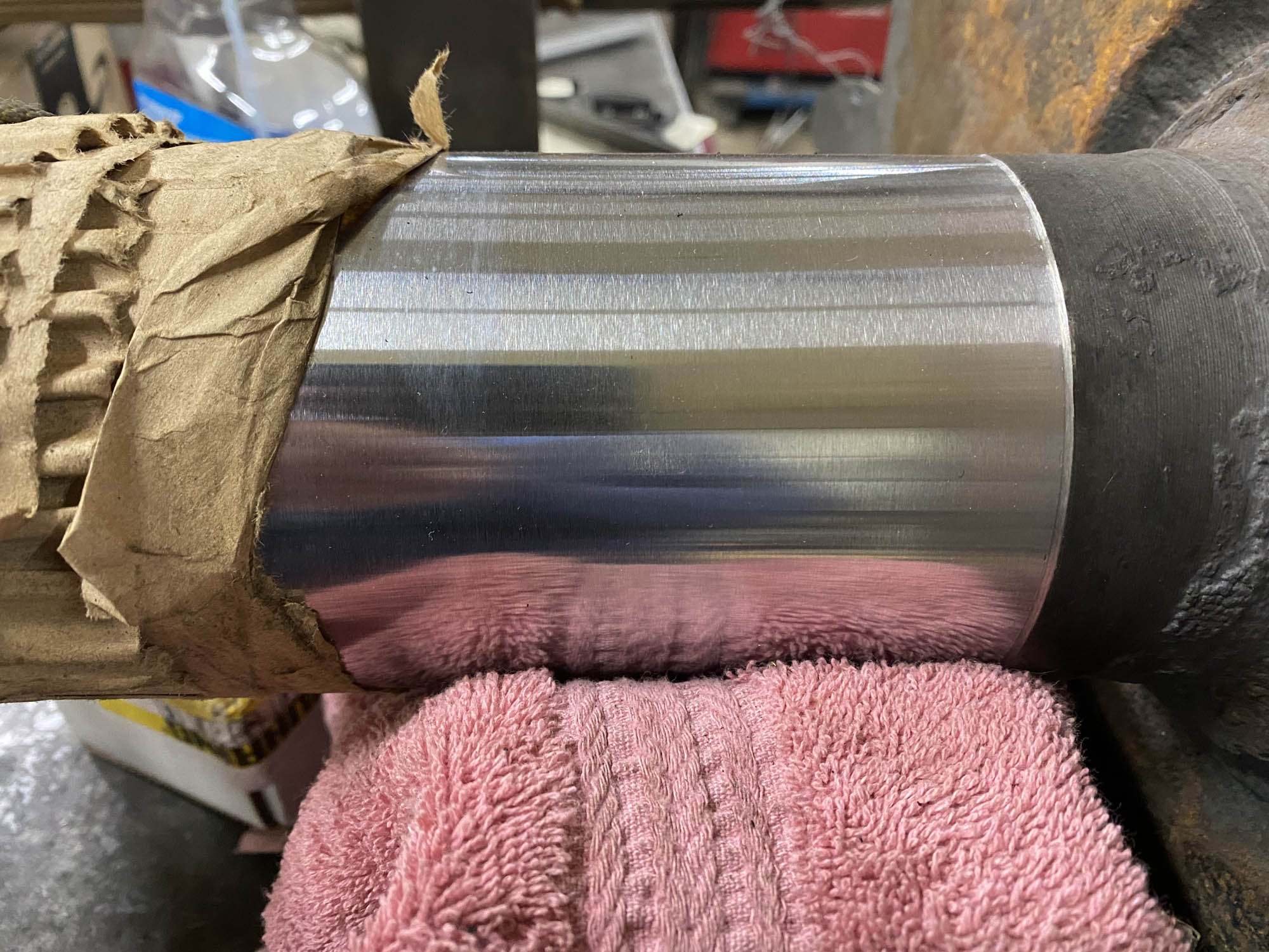
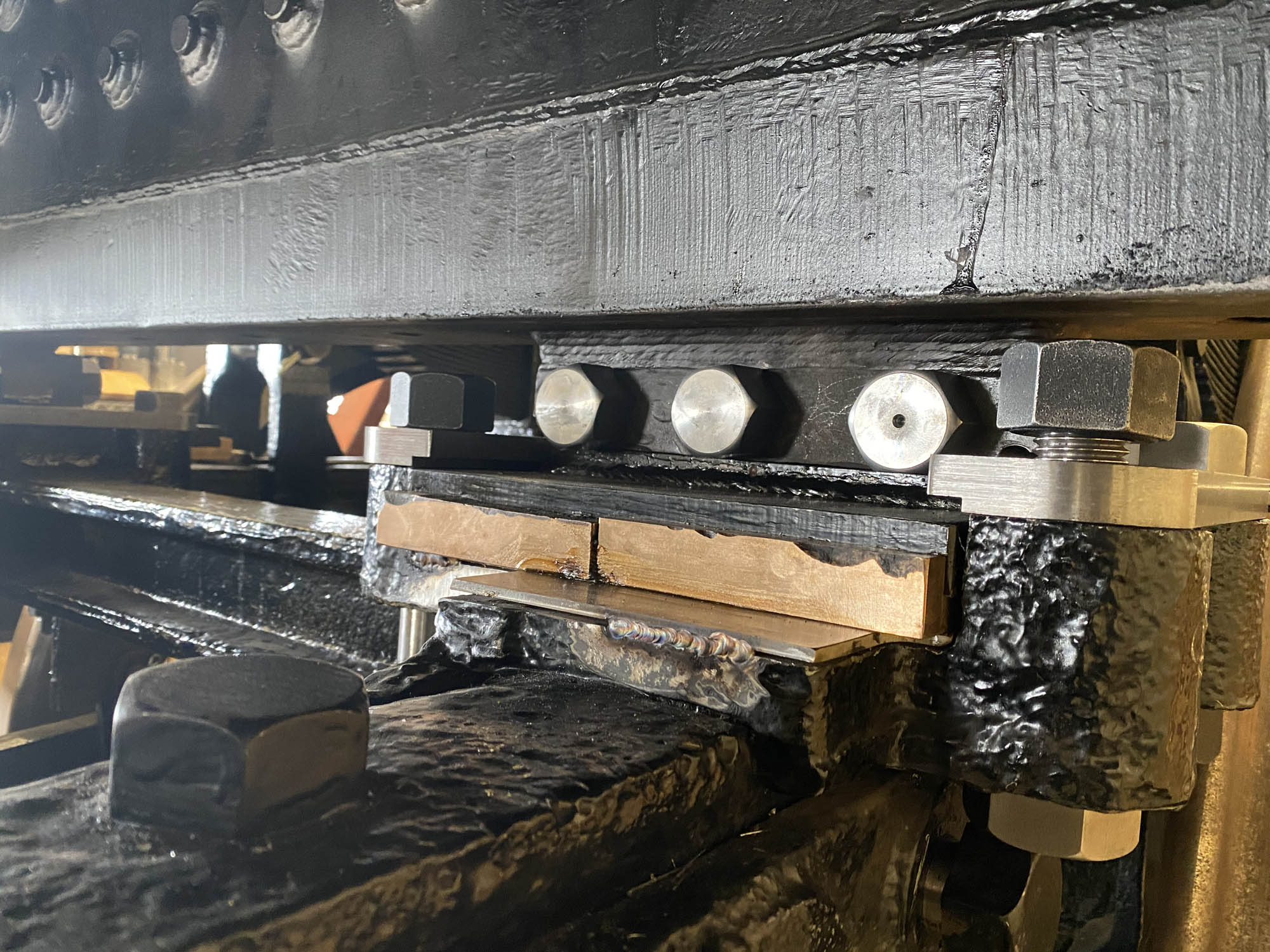
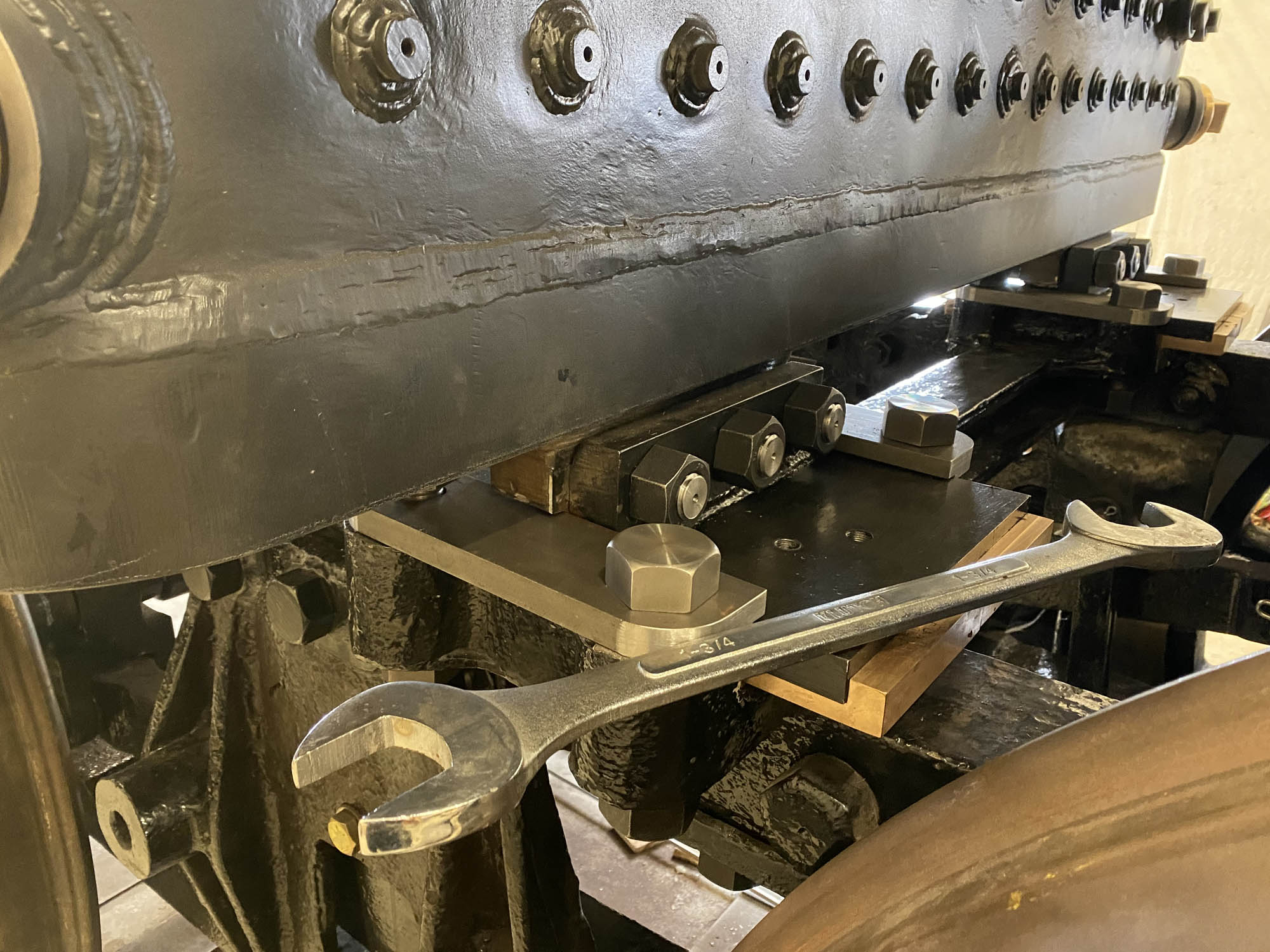
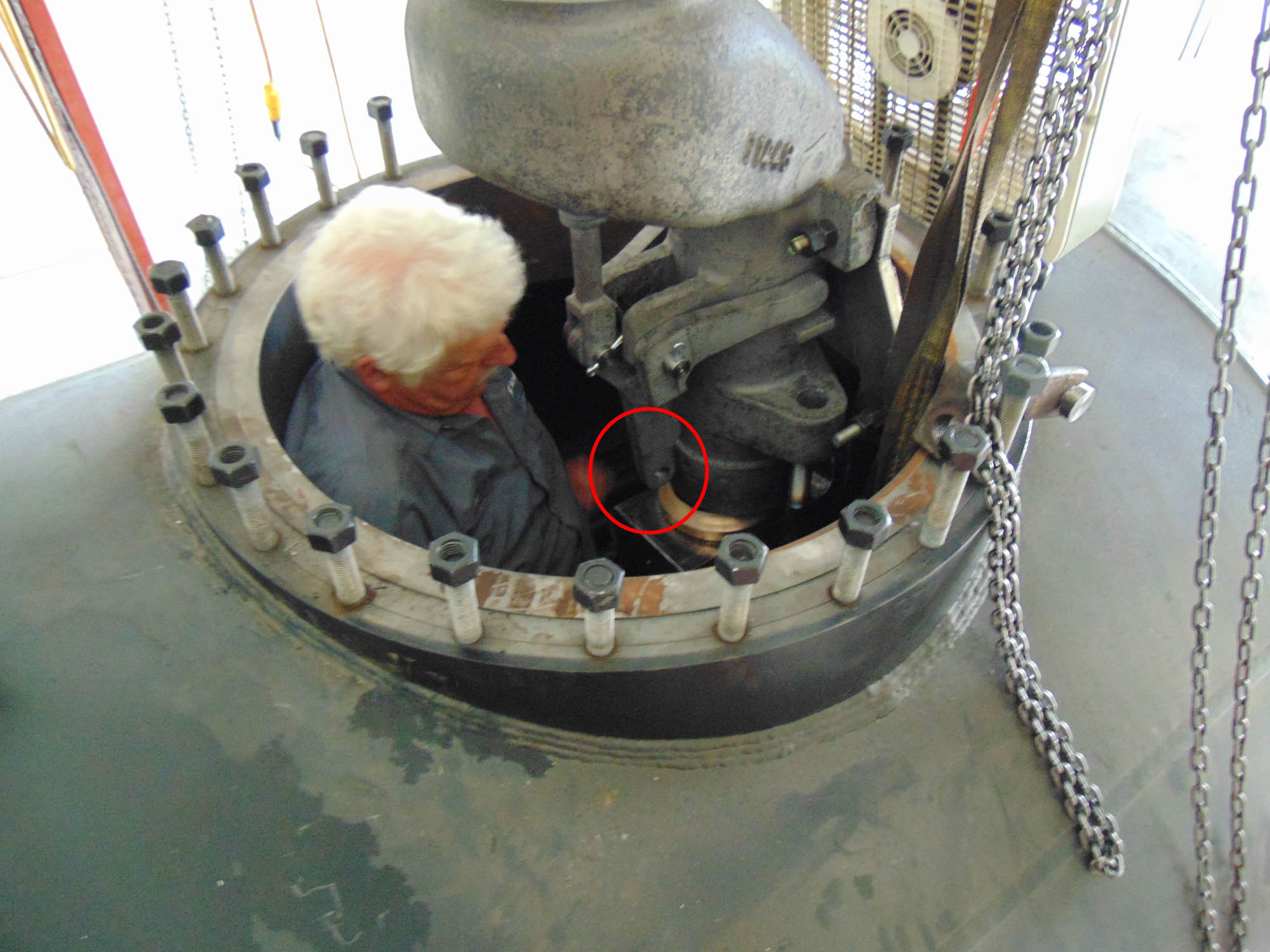
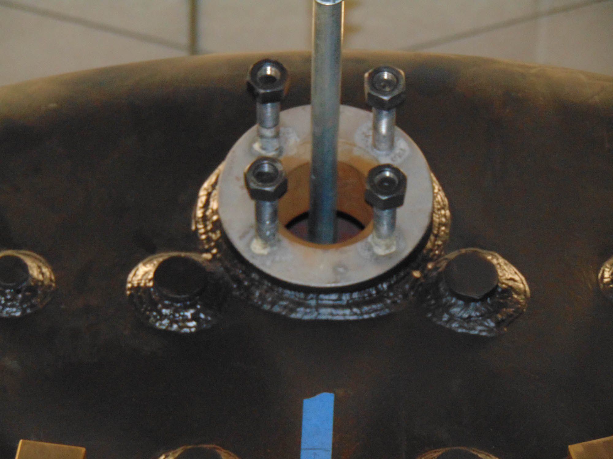
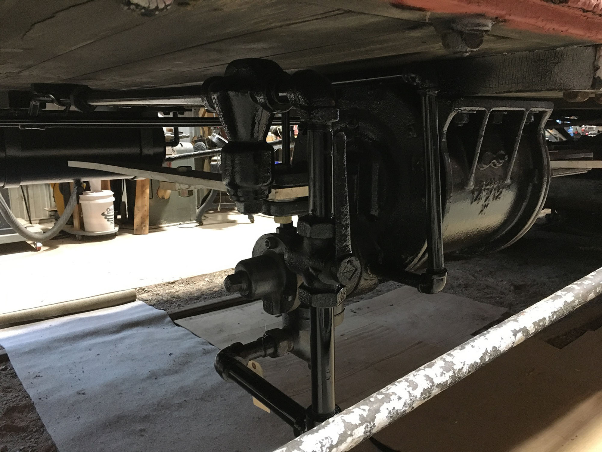
Under the car significant progress was made on the air brake system as the brake foundation plan was finalized. With the design set volunteers proceeded to reposition the air cylinder and complete all of the air piping under the car. The next steps will be to fabricate and install the brake levers and rods to the trucks.
-
-
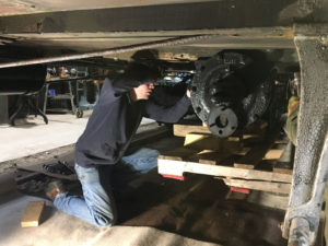
Mike M. moves the DULUTH’s air brake cylinder.
-
-
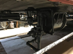
The air cylinder and piping work completed under the DULUTH.
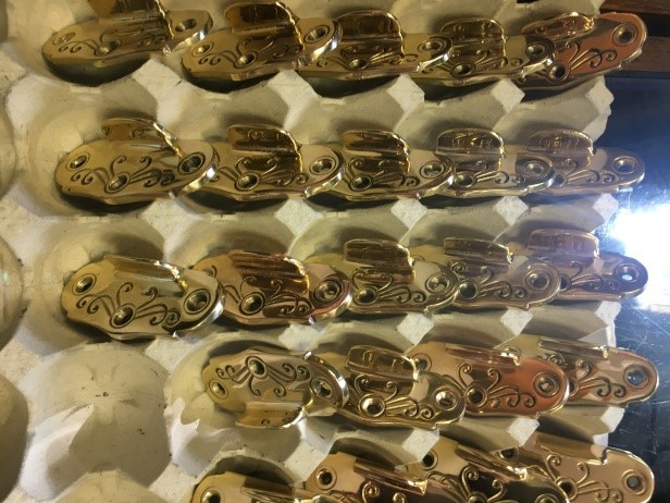
Volunteers working at home made significant progress of restoring hardware for the car. Work completed ranged from restoring oil lamp roof vents to over 300 pieces of berth and sleeping compartment hardware.
-
-
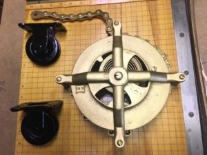
Restored berth pulley
-

-
Restored and polished window lifts
Related Links:
DSS&A DULUTH Restoration Updates
DSS&A DULUTH Roster Page
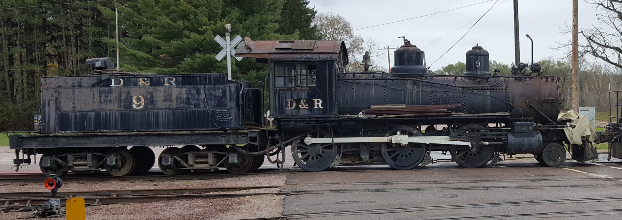
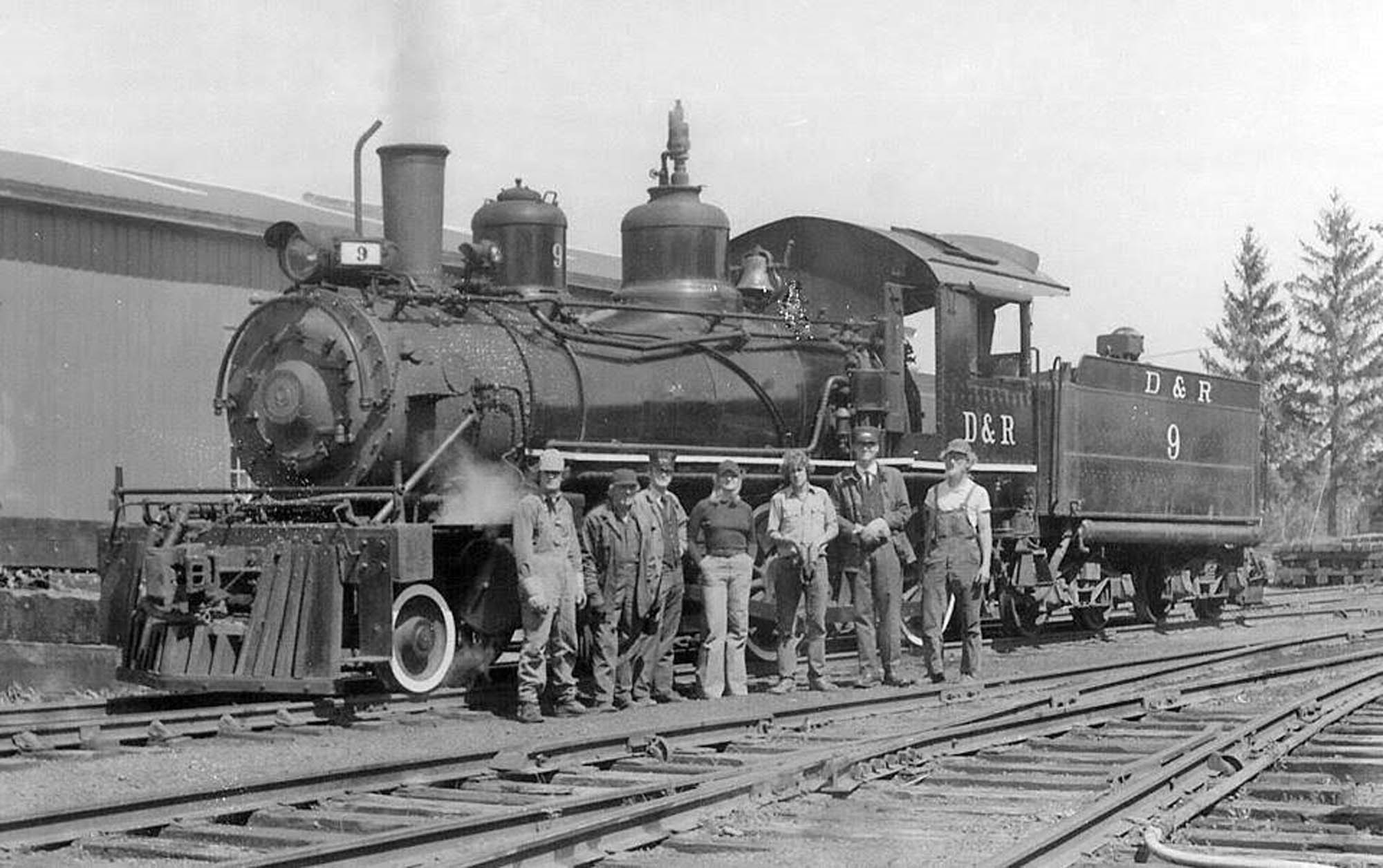
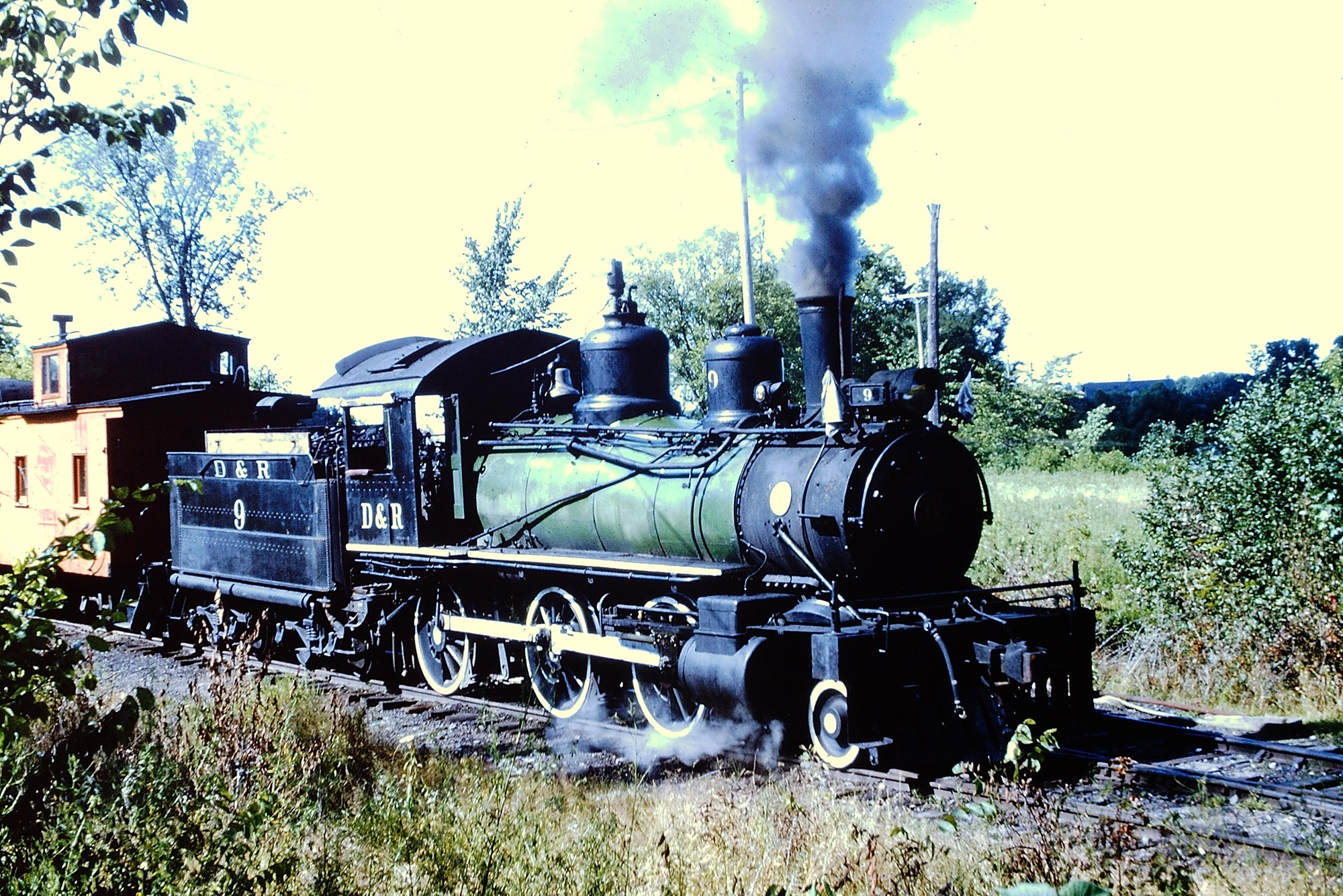
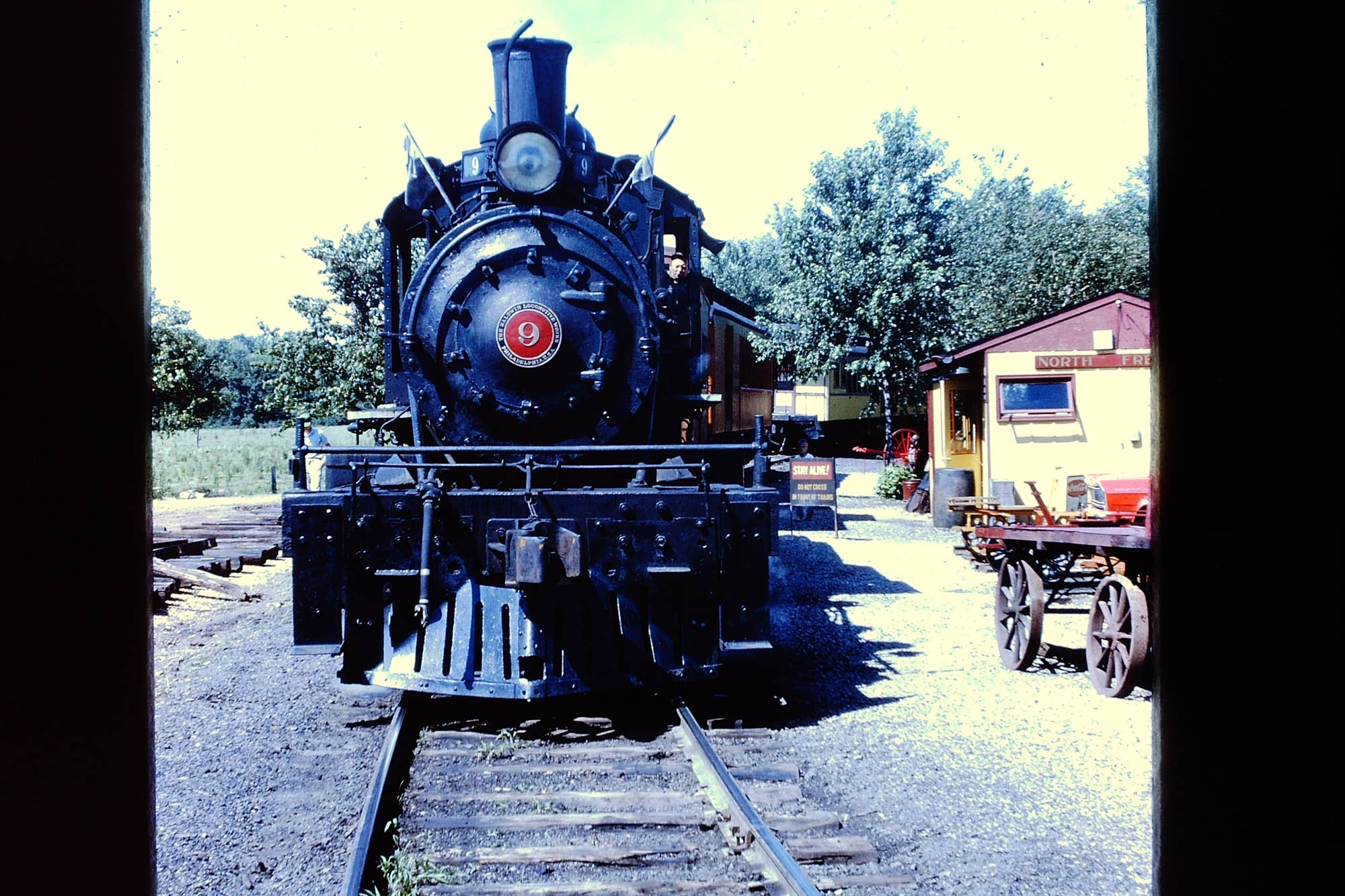
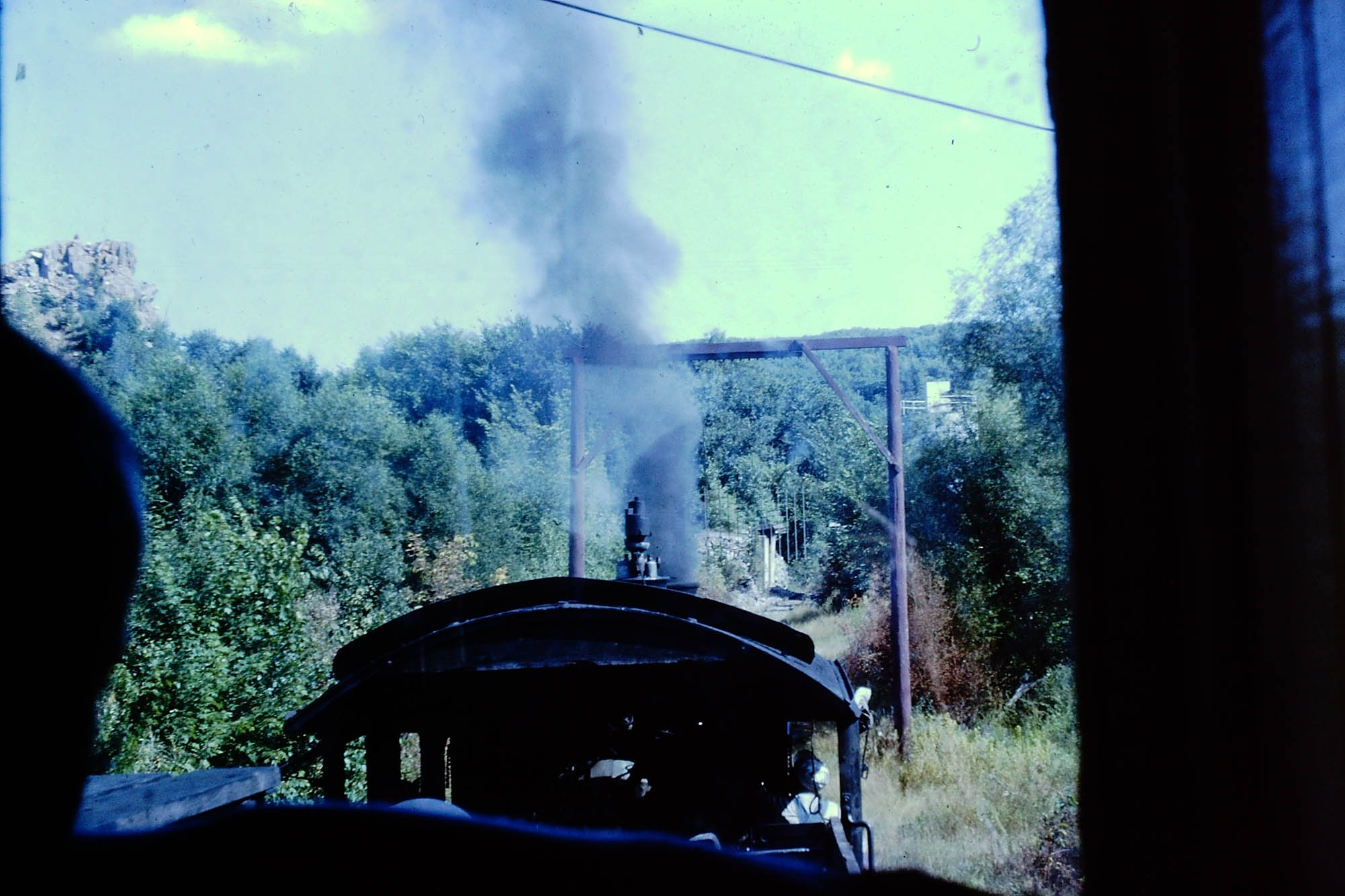
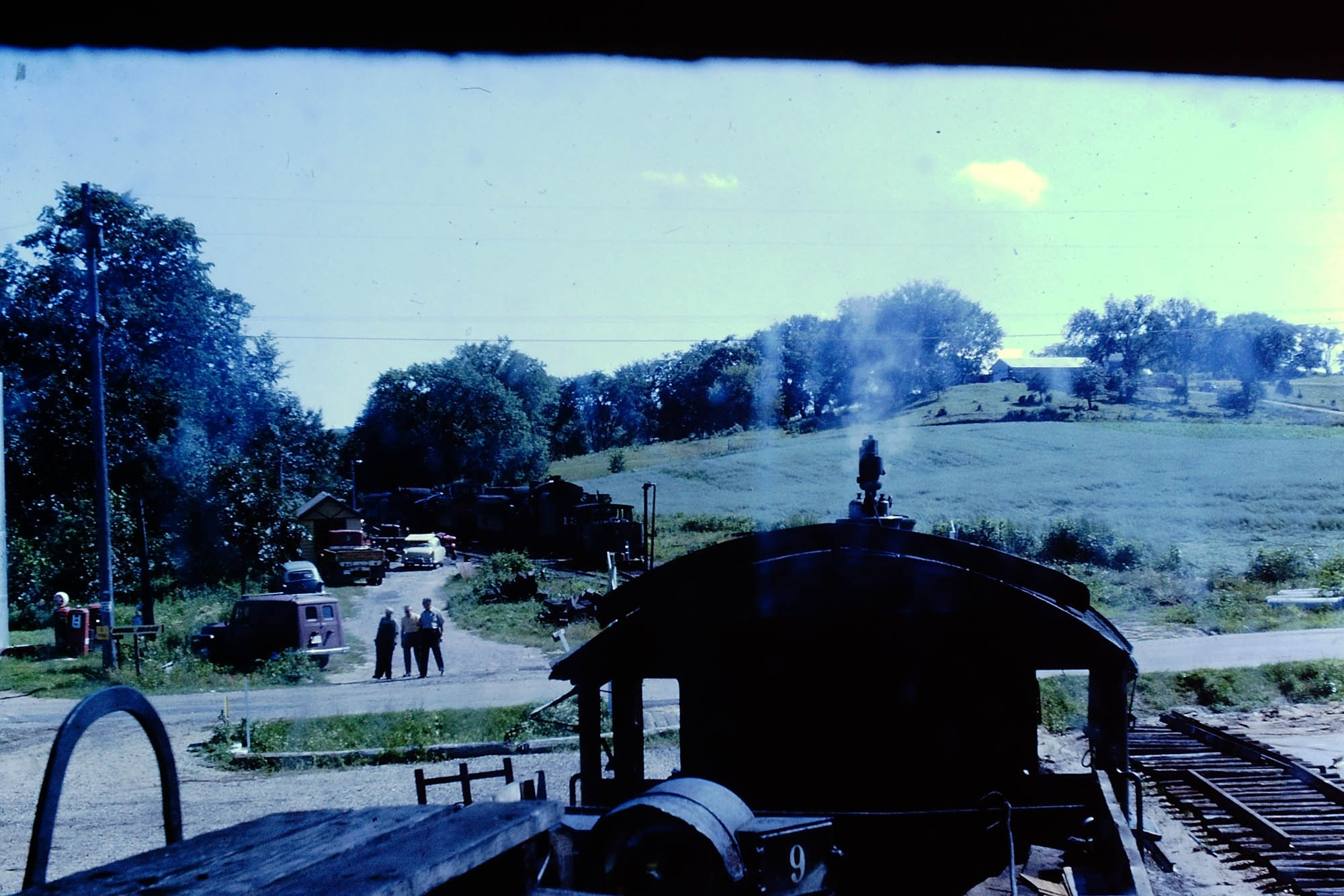
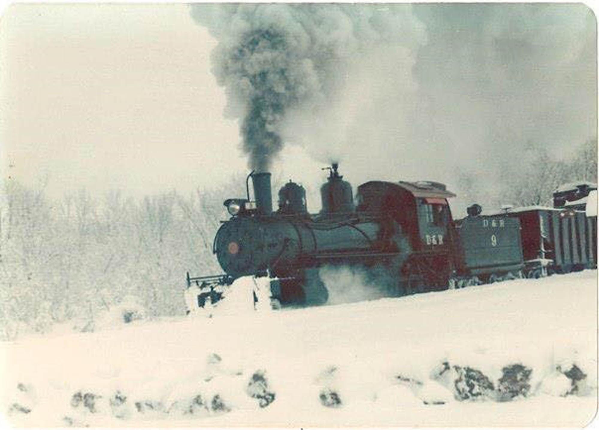
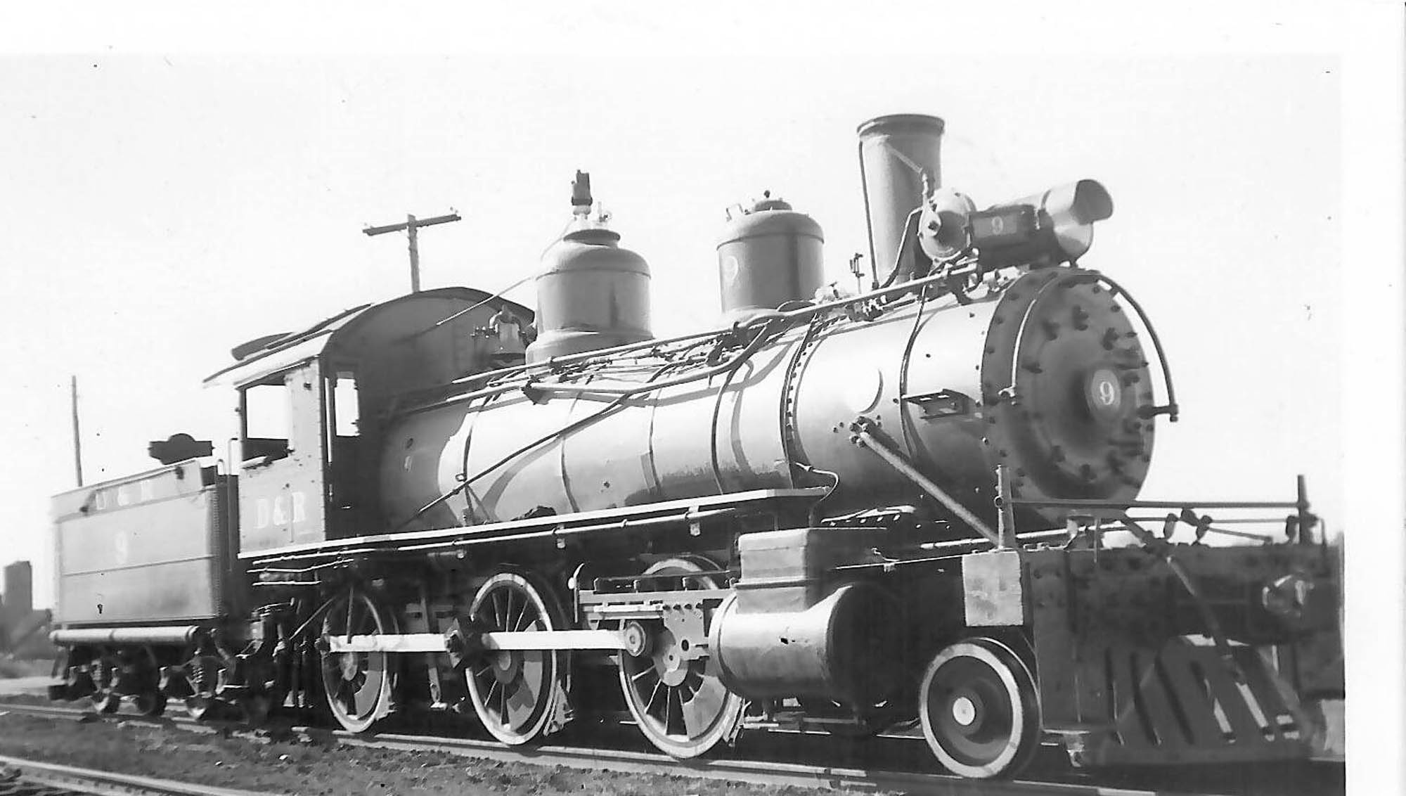
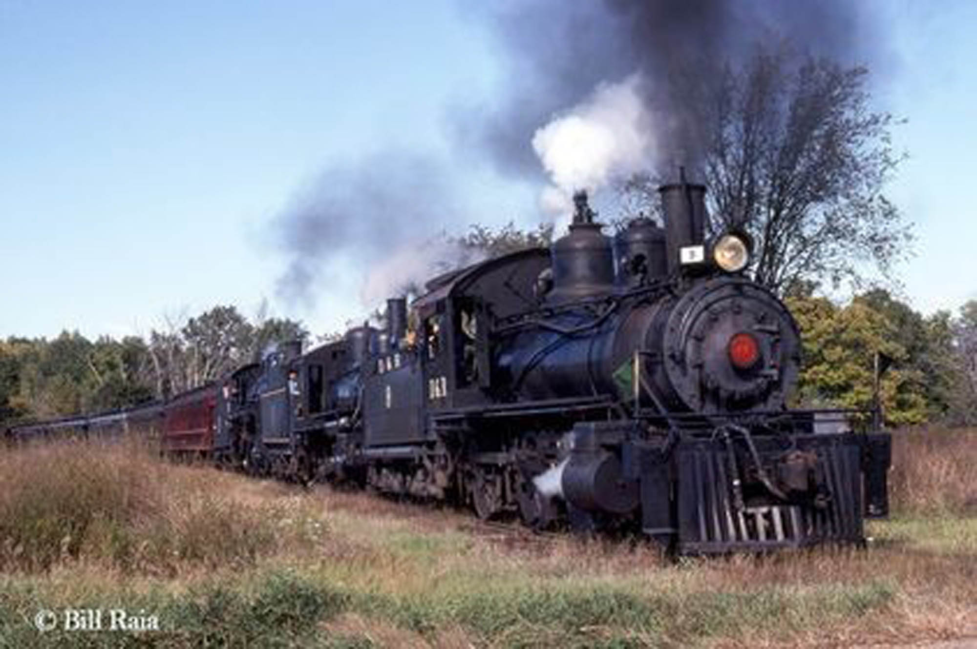
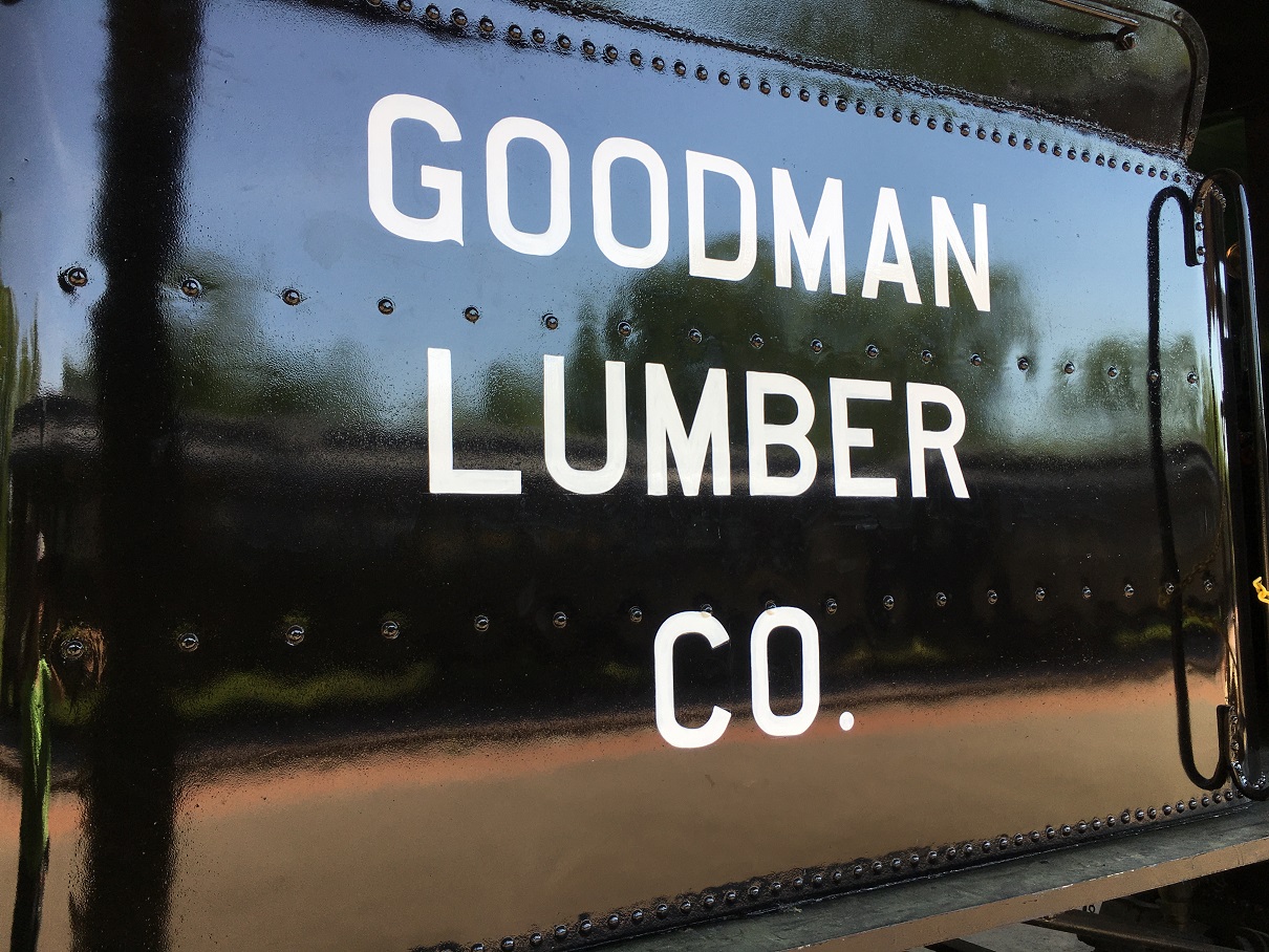
Goodman Lumber Co. Shay #9
The water tank was bolted to the frame and the tank was re- lettered. The rear sand tanks were restored and re-installed as were the rear steps. The whistle was removed and a new lever (previously missing) was replicated. The wood tool box that was mounted on the rear of the Shay was constructed (to be installed in 2021). Main air reservoir and the front head light removed for restoration and re-painting. Lastly, a pair of Lima gauge lamps (for the steam gauge and water glass) were acquired and restored.
-

-
Chris adds lettering to the Goodman Shay tank.
-

-
Freshly painted tank of the Goodman Shay .
Related Links:
Goodman Lumber Co. #9 Roster Page
Lake Superior & Ishpeming coach #64
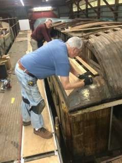
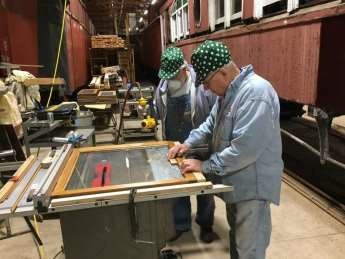
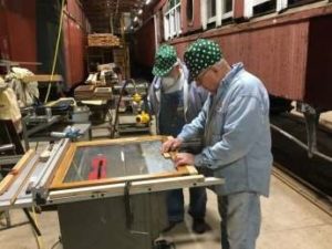
All of the seat castings and cast heat guards were de-burred and painted. All of the upper and lower sash (inner) windows were stained, varnished and glazed. The lower roof repairs were completed on the NE corner of the car and the lower roof repairs in the NW corner of the car are in process.
-

-
Tom sanding one of 70 window frames completed this year for the LS&I #64.
-
-
A sample of the completed and painted seat castings for the LS&I #64.
-

-
Roof repairs to LS&I #64 in progress with Jerry and Jack.
-
-
David works on roof repairs to LS&I #64.
-
-
The team of Jeff H. and Owen glazing LS&I #64 windows.
Related Links:
LS&I #64 Roster Page
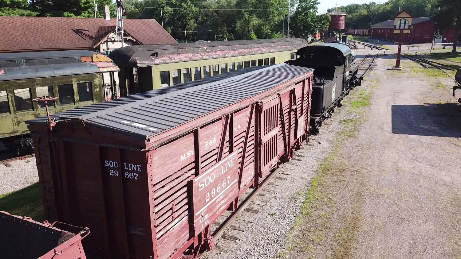
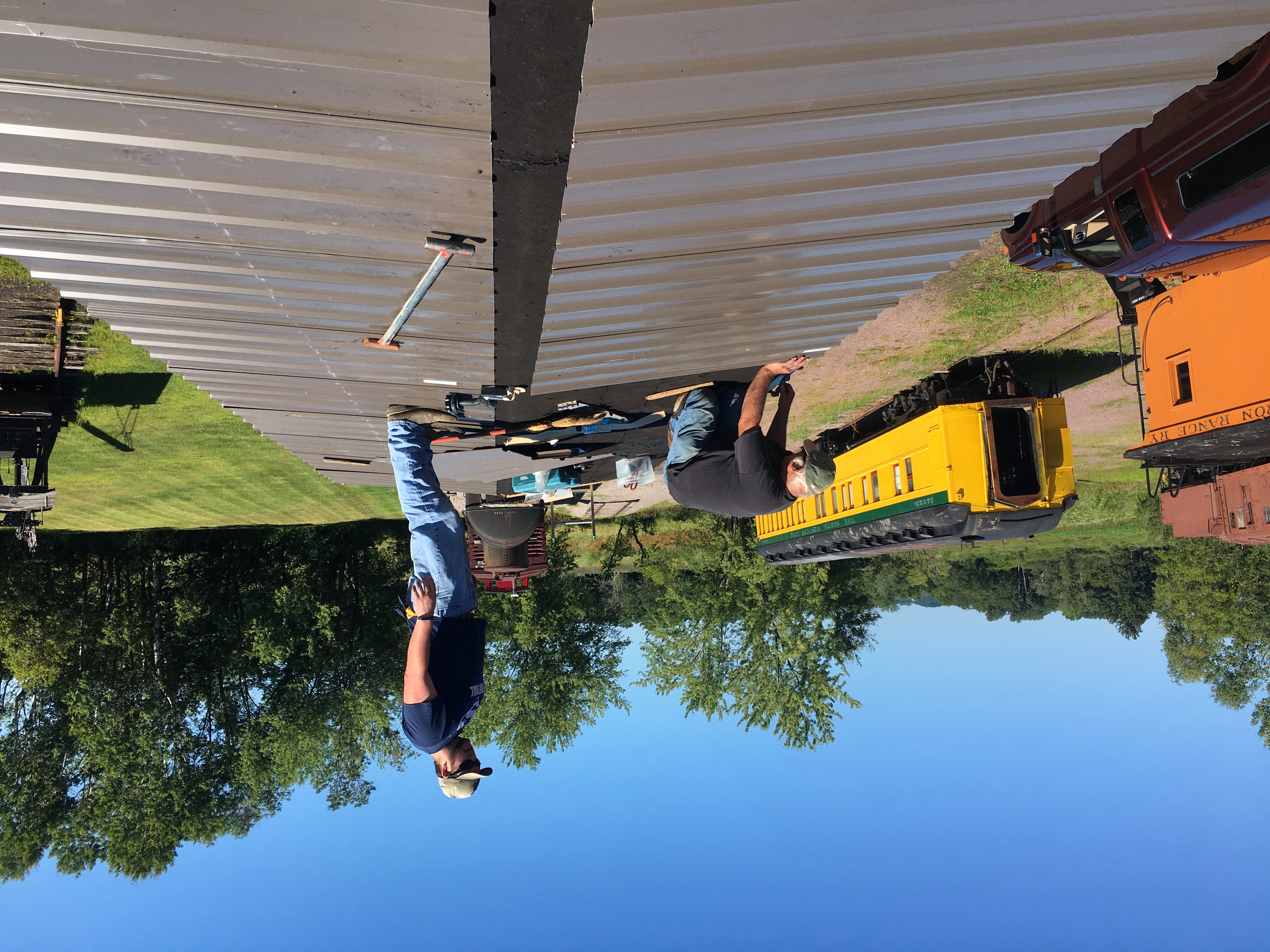
Soo Line stock car #29667
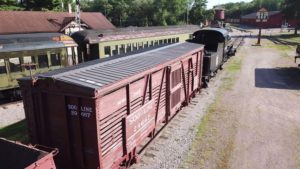
Installed a new steel roof on the Soo Line stock car.
-
-
The completed roof project on Soo Line #29667.
-

-
Richard (L) and Patrick (R) working on installing the steel roof panels on the Soo Line stock car.
Related Links:
Soo Line #29667 Roster Page
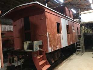
Soo Line caboose #203
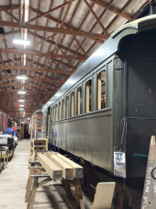
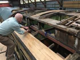
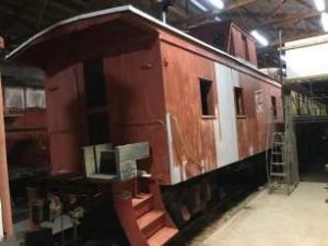
The old rolled roofing material was removed off of the entire roof. More siding repairs and replacement were made and the side windows were removed (for restoration). A replacement oak end beam (for the north end) was purchased and is in the process of drying out so it can be cut and installed in 2021.
-
-
Current state of the work in process on the Soo Line #203.
Related Links:
Soo Line #203 Roster Page
Milwaukee Lake Shore & Western coach #63
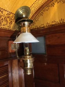
An original Dayton Mfg. Company side lamp was restored and installed in the MLS&W #63 coach. This is the first of eight side lamps needed for the car.
-
-
Dayton Mfg. Company side lamp inside MLS&W #63.
Related Links:
MLS&W #63 Restoration Updates
MLS&W #63 Roster Page
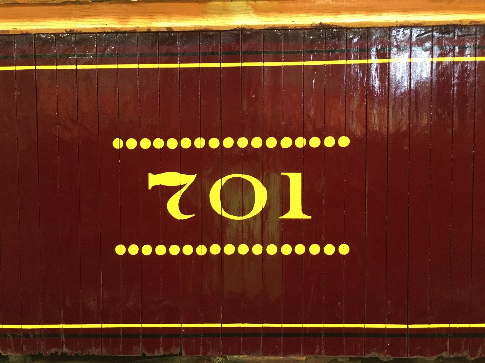
Duluth South Shore & Atlantic coach #701
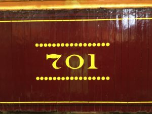
Portions of the east side of the DSS&A #701 coach were restored and repainted so the original style numbers could be painted onto the car.
-
-
Portions of the east side of DSS&A #701 painted and lettered to match historic photos.
Related Links:
DSS&A #701 Roster Page
Badger Fish Car #2
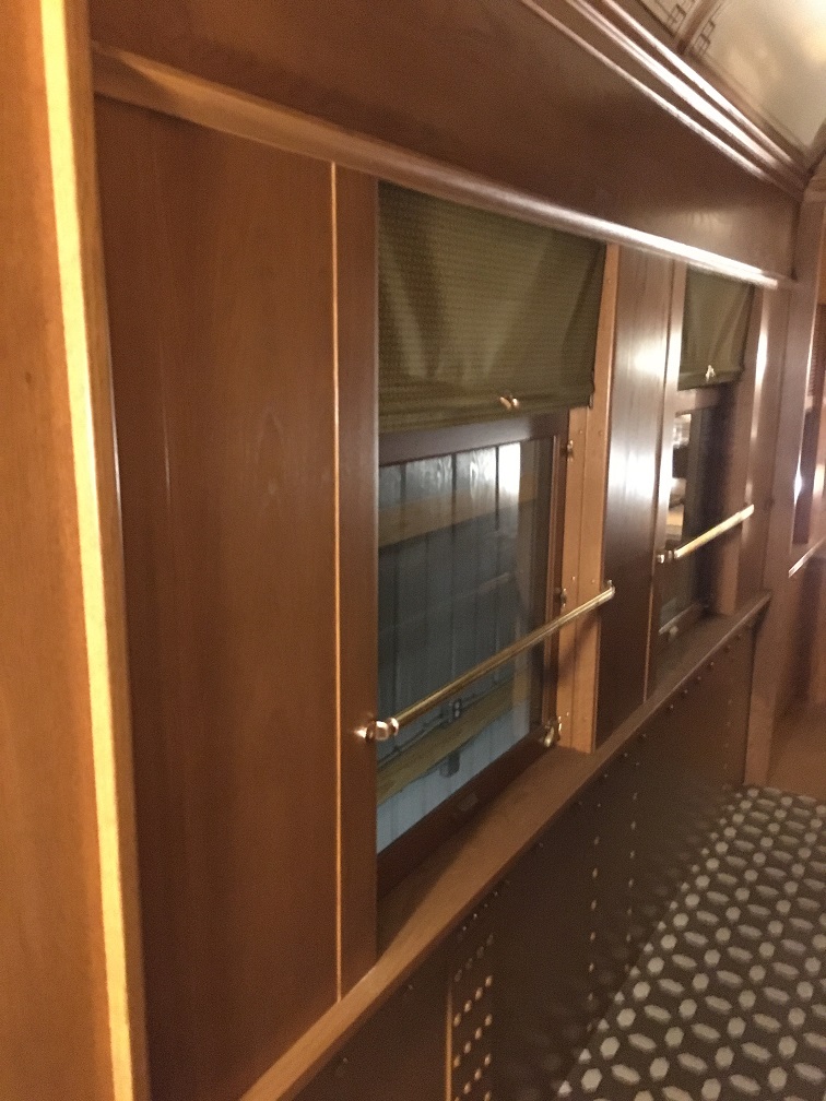
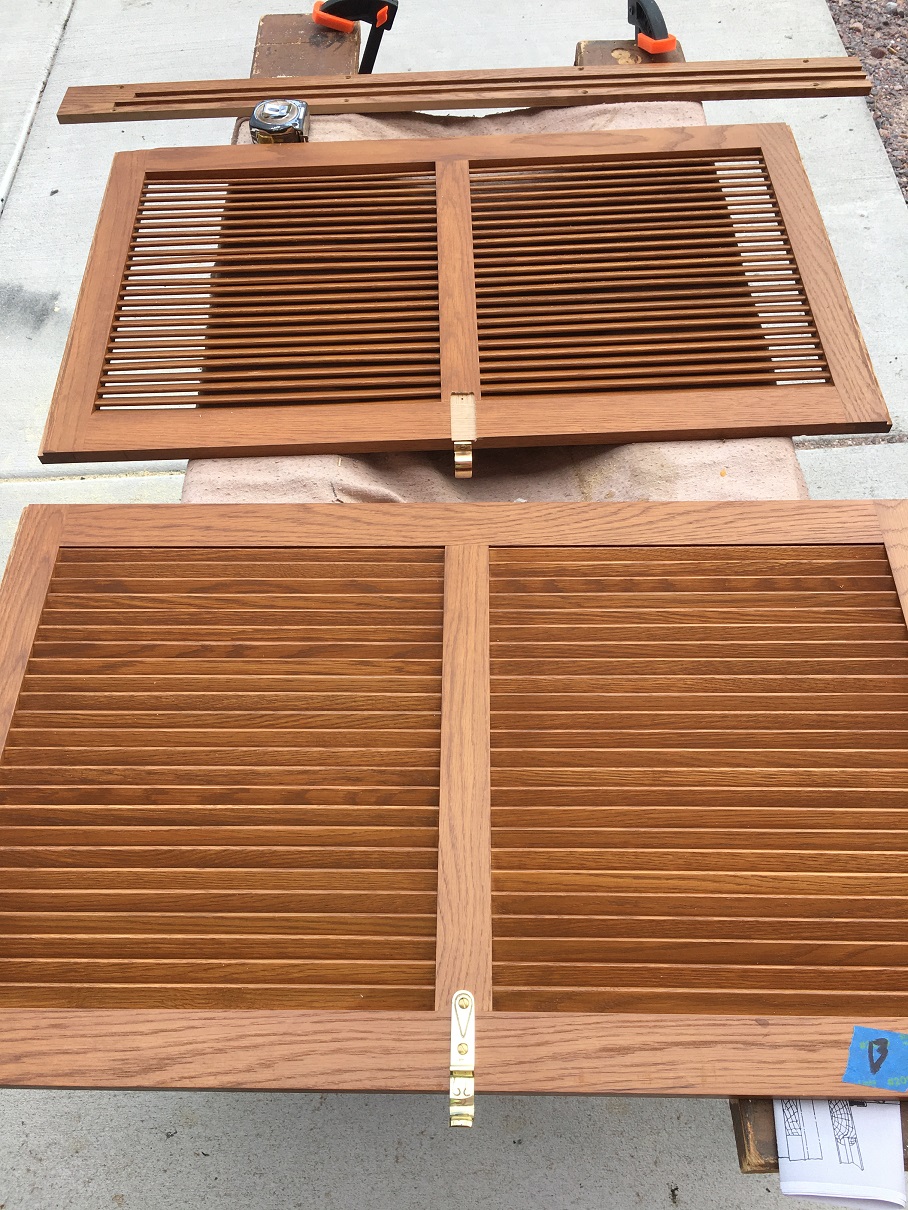
Restored and installed (8) window guards in the car. Installed the missing step trap latch and in the process of installing the blind hardware (lifts and springs) on the wood blinds (8 of 21 completed).
-
-
Two of the window guards installed on the Badger #2.
-

-
The Badger #2 window blinds with the hardware installed.
Related Links:
Badger #2 Roster Page
Car Shop/Miscellaneous
- Scaffold Upgrades made and the elevated work area was
- Electrical service provided to the large ventilation fan (south end)
- Electrical service provided to the south end work deck area
- Restored and repainted the two vestibule doors for the Soo Line #2017
- Installed tarps on the CB&Q #1490 and the KGB&W #76 baggage cars
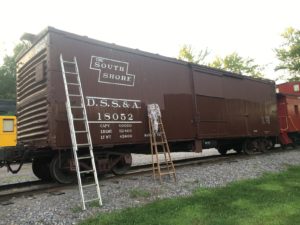
- Applied clear coating to the: DSS&A #18052 (box car), DSS&A #996 (gondola) and the east side of the Soo Line #99085 (caboose).
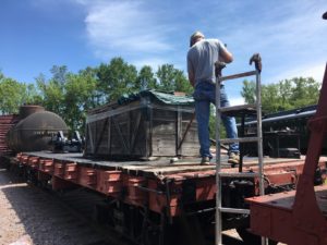
- Applied deck preservative and installed a new covering over the crate on the DM&IR flat car. Moved several pallets of passenger car parts from the Car Shop to the new Storage Building
- Cleaned and organized the interior of the C&IM business car
- Continued to work on removing deteriorated sills from under the C&NW #1099
- Repaired and sealed gaps under the west side wall of the Car Shop
- Added ballast and sealed the south end doors of the Car Shop
- Made (3) new display sign bases
- Made bases for the (2) new donation boxes
-
-
Jeff H coating the deck of the D&IR flat car.
-
-
Clear coating in process on the DSS&A box car.
Related Links:
Soo Line #2017 Roster Page
CB&Q #1490 Roster Page
KGB&W #76 Roster Page
DSS&A #18052 Roster Page
DSS&A #996 Roster Page
Soo Line #99085 Roster Page
D&IR #5537 Roster Page
At-Home Work
With the pandemic keeping volunteers at home more than normal, many of the volunteers stepped up to work on restoration projects in their home workshops. Following is a list of some the off-site work completed during the year:
- EJ&S #2: Made, stained and varnished new mahogany window stops (20), made, stained and varnished blind stops (42), Purchased, polished and installed (10) window blind catches, Installed 10 window blind lifts, Finished construction of southeast corner all wood steps and seat castings sent out for machining and de-burring,
- DULUTH: Restored coach lamp roof vents, restored sleeping compartment berth hardware (in process), and a Barney & Smith corner
- Goodman #9 Shay: Designed and constructed the rear tool box and restored the Lima gauge lamps
- LS&I #64: Stencils cut for lettering the car, windows refinished
- Badger #2 Fish car: Restored the window guards for the car, restored the blind hardware (lifts and springs).
- DSS&A #701: Stencils developed and cut for the car numbers
- GN #3261: Machined, de-burred and polished baggage rack
- Created drawings for the: DULUTH, LS&I #64, Soo Line #203, EJ&S #2 and the Goodman Shay #9.
Fundraising (donations received)
Dailey Foundation, Giving Tuesday, DULUTH Buy-A-Berth and donations to support the Restoration Department projects
Looking ahead to 2021 we look forward to resuming work on the active projects. Unfortunately, funding for the Restoration Department projects will be negatively impacted by the loss of income from the 2020 shut down and the weekend only schedule in 2021. In 2020 the Restoration Department used over $12,000 of designated funds (from savings accounts) and we’ll need your help now to keep the Restoration Department projects moving ahead in 2021! This is where you can really help. I hope you will be able to help the Restoration Department continue to make significant progress in 2021. Won’t you please consider making a generous contribution today?
Donations supporting the Restoration Department can be submitted online or by mail to the MCRM office. Be sure to designate your donation for the “Restoration Department”.
Printable Donation Form (PDF)
Mid-Continent Railway Historical Society
PO Box 358
North Freedom, WI 53951
In closing, many thanks to everyone that volunteered their valuable time and contributed funds towards the restoration work at Mid-Continent in 2020. Have a Happy, Healthy and Safe Holiday and a Happy New Year!!! I’m looking forward to seeing you at Mid-Continent in 2021!! The first 2021 work session will be held on April 3rd.
William Buhrmaster
MCRM Restoration Department